


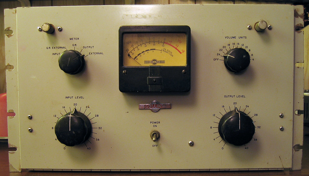
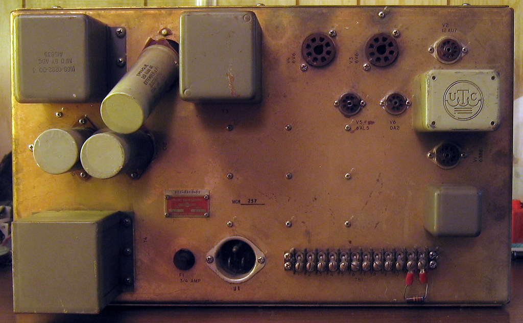
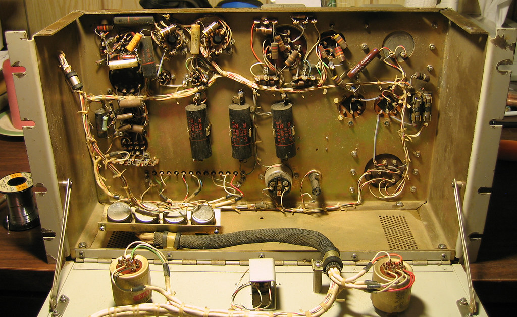
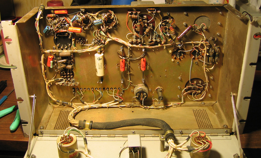
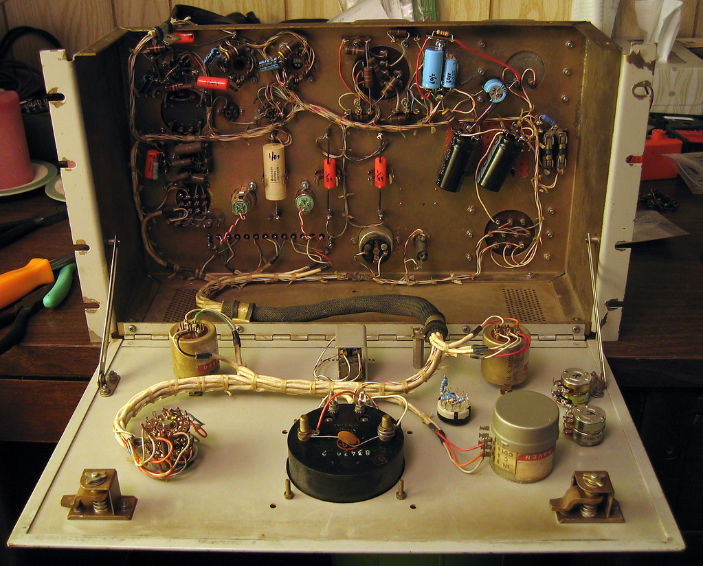
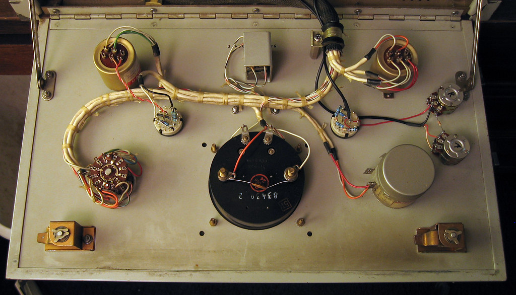
Here's one I just finished for a client. These pics chart the progress. Looked like it had lived in a barn for awhile; had mud dauber nest residue inside. He wanted modern connectors on the back and more controls on the front, so here's what I came up with. All new caps, several of the PSU resistances were broken, or way off. Note on these that the door support on the right side is extremely close to the rectifier(!), and if bent incorrectly, will make a shorting contact when the door is shut. I am not a fan of these particular Daven input and output ladders, as they are the only Daven types you cannot easily open and clean. Not sure why they were used here.
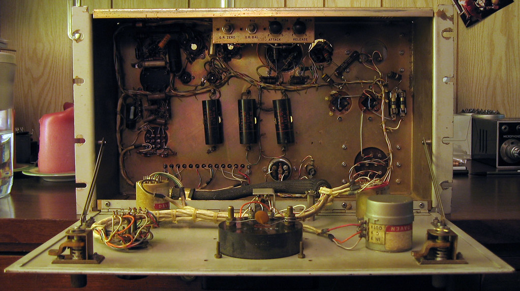
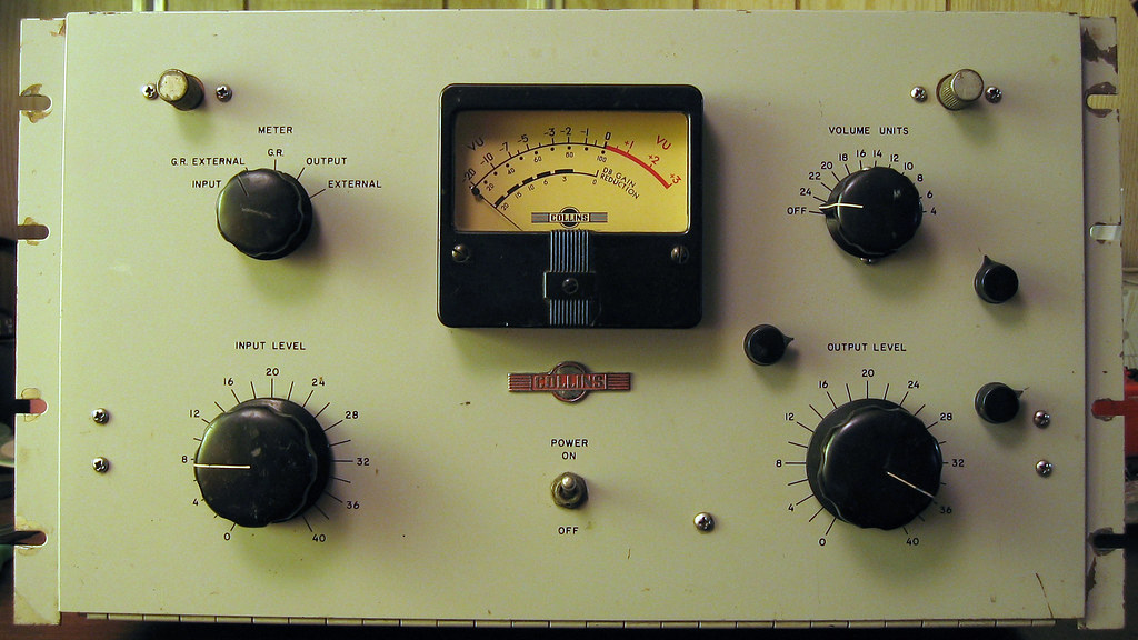
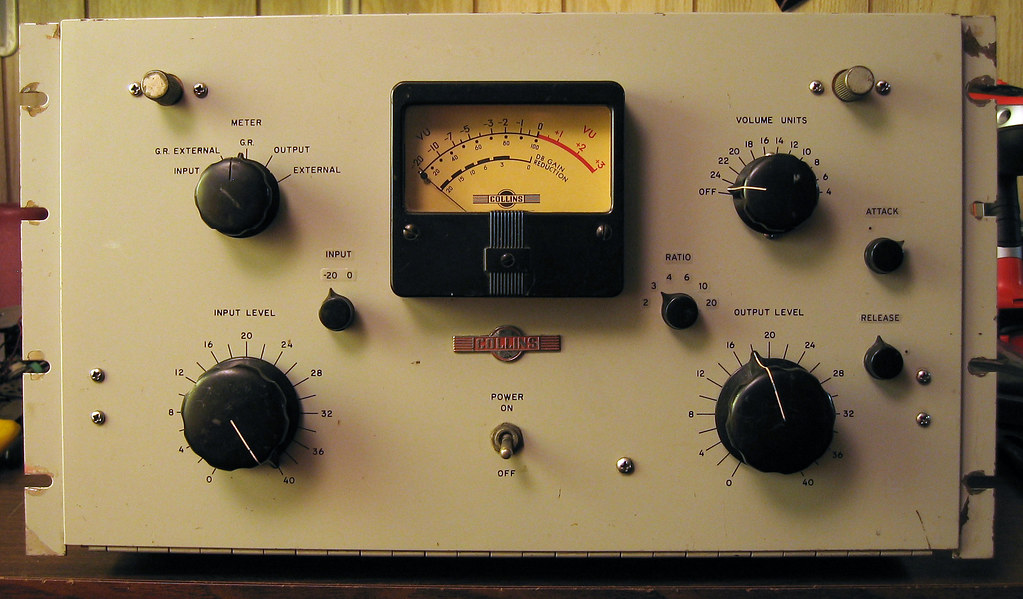
The dots at the attack and release pots mark original slowest attack and fastest release. The ratios are simply taps on the side chain bias voltage divider, and were plotted using the method described in the manual, which is available online. Note the GR meter marking is only really (kind of) accurate at the stock ratio (highest), and with steady state tones. If you compare the meter markings with the markings for the 26J/356E compressor (find and see manual) you will see the difference for the lower ratios. These sorts of meters give more of an idea of action, versus actual specific information.
The dots at the attack and release pots mark original slowest attack and fastest release. The ratios are simply taps on the side chain bias voltage divider, and were plotted using the method described in the manual, which is available online. Note the GR meter marking is only really (kind of) accurate at the stock ratio (highest), and with steady state tones. If you compare the meter markings with the markings for the 26J/356E compressor (find and see manual) you will see the difference for the lower ratios. These sorts of meters give more of an idea of action, versus actual specific information.
