Balanced High Pass Filter

GroupDIY Audio Forum

Help Support GroupDIY Audio Forum:

This site may earn a commission from merchant affiliate links, including eBay, Amazon, and others.
Excellent!

Here's a link to the circuit with revised XFMR1 parameters:
https://www.circuitlab.com/circuit/k9dgws/2nd-order-hpf-v2/

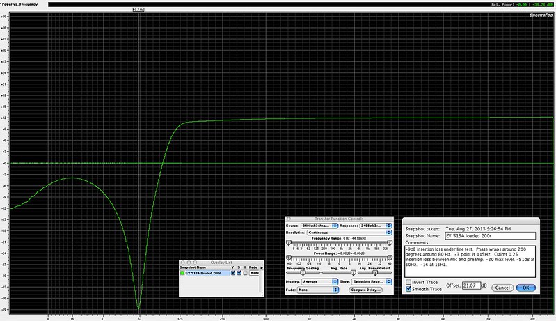
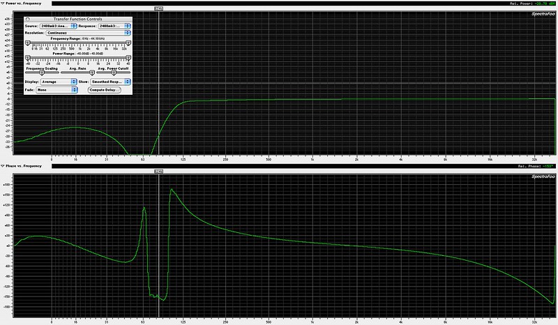
The resulting plot is attached. It looks considerably more steep and the cutoff frequency is more apparent at 100Hz.

Thanks for the assistance!
 

Attachments

  • 2nd-Order-HPF-v2.png
    2nd-Order-HPF-v2.png
    22.8 KB · Views: 22
Referencing this post:

http://www.groupdiy.com/index.php?topic=38211.msg471679#msg471679

I noticed the data sheet for the Electro-Voice 513A mic filter which gives some different values (this goes to an auto-download on my laptop, but not on my phone):

www.electrovoice.com/downloadfile.php?i=970505‎

I measured one from 1974 with a 150ish source and a 200 ohm load, at medium mic level. 

The inductors measure about 9 ohms, 325mH at 120 Hz, and 120mH at 1 kHz.  The caps in mine are tantalum, two measuring 31mfd, and the other 18 mfd. 

full size

9611076267_dbee91c622_c.jpg


full size

9611076147_762ab0c5aa_c.jpg

 
emrr said:
I noticed the data sheet for the Electro-Voice 513A mic filter which gives some different values (this goes to an auto-download on my laptop, but not on my phone):
I measured one with a 150ish source and a 200 ohm load, at medium mic level. 
That's exactly what the simulation predicts. Big notch at about 60Hz. Maybe they thought it would prevent hum pick-up...?
The more complex structure makes it less sensitive to output loading than the Shure counterpart.
 
From the text I might guess they 1) wanted an extreme slope and 2) didn't figure the stuff below 30Hz mattered much.  It's curious they didn't go with an L/C/L Pi filter, perhaps the slope didn't meet requirements and/or the loading would be more sensitive?  Or L quality and size would become prohibitive?

At higher load value, you get typical resonant boost spike at cut off, and a dip above the cutoff. 
 
pece4681 said:
Is it possible to substitute the inductors for resistors to get a -6 dB/octave filter?
You asked the same question on the micbuilders site, and I'll give you the same answer.
Yahoo is down, that's probably why you didn't get my answer.
Get rid of the inductors, change the caps for 1uF; depending on the actual value of the input impedance of your preamp, that will put you in a ballpark.
 

Latest posts

Back
Top