Gates SA-70 Western Electric 141-A mash-up and tweak

GroupDIY Audio Forum

Help Support GroupDIY Audio Forum:

This site may earn a commission from merchant affiliate links, including eBay, Amazon, and others.

emrr

Well-known member
Joined
Apr 12, 2006
Messages
8,749
Location
NC, USA
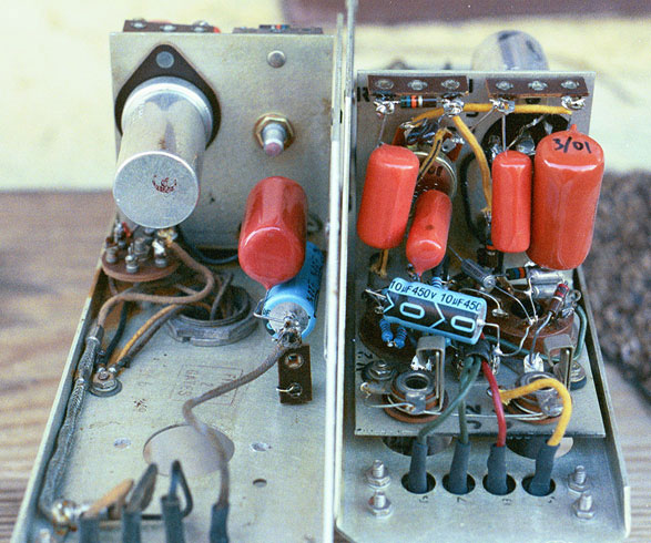
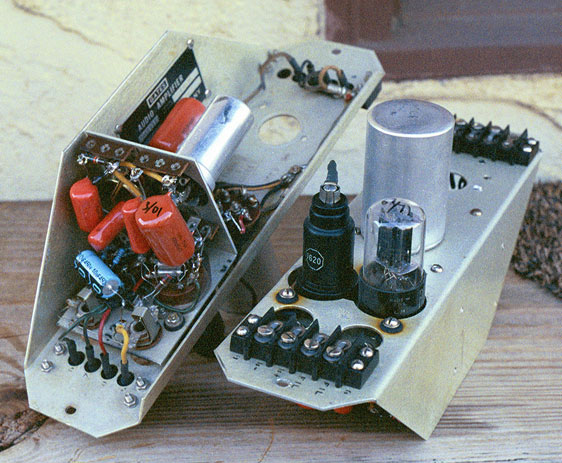
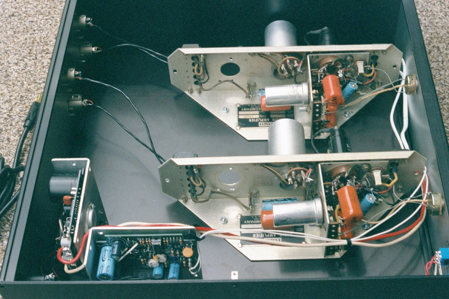
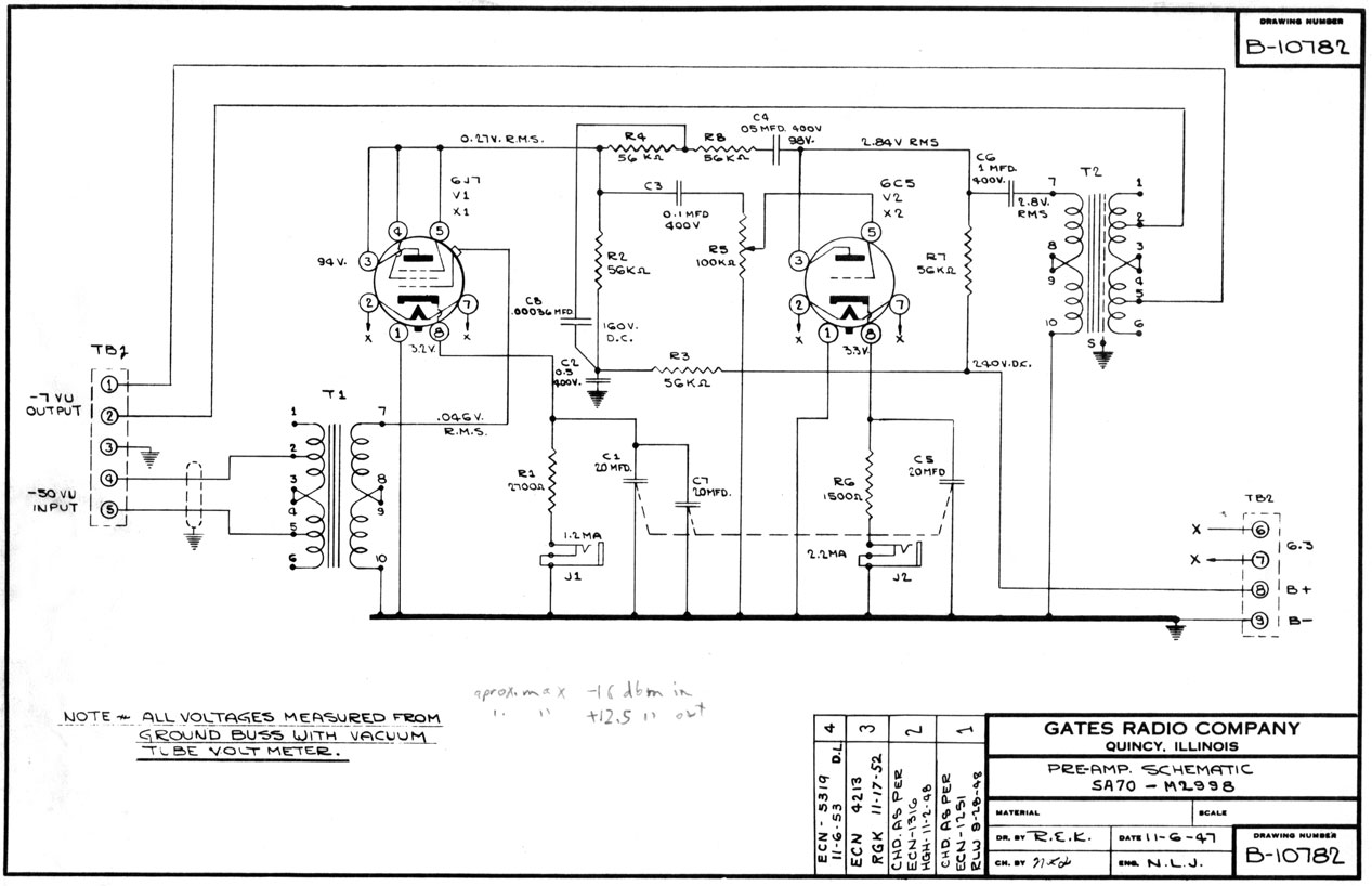
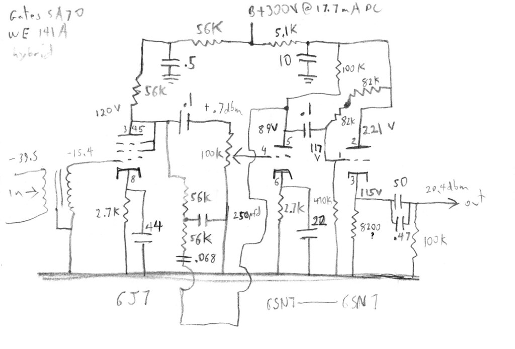
The 141-A has had more discussion lately, and someone asked my about a version I built awhile back, which I've never posted.  This isn't so much a new design, as a mash-up and tweak necessitated by need.  About 10 years ago I had some SA-70A's that were missing output transformers, and made good test beds. 

Here's my only drawing, as evidence.  Looks like I documented 60 dB max gain.  Note the question mark next to the 8K2 output cathode resistor.  I think that's what I used, but I can't be sure.  The 250 pfd in the feedback path was arrived at by crude measurement and by ear, to compensate for high losses in the input transformer.  Same story on the 0.068 in the feedback path, for lows.  Those will be different values for a different input, and maybe not even needed.    I liked this approach more than I did my 141-A clone, mainly because the sound did not change drastically with gain setting, as it does in the 141-A.  These went to a new home around 2003, and I have not revisited this approach since. 
5433956772_317f749f82_b.jpg


2628705484_18f183c418_o.jpg


2628705738_35c1b166ee_o.jpg


2628705638_a50fd9e932_o.jpg


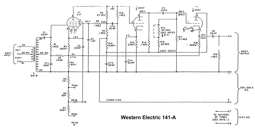
For comparison:

we141a.jpg


3329545281_dfd7d214a7_o.jpg


here for Western Electric 141-A thread
here for Gates SA-70
 
Eagle Eye Joel noticed I have 82K in the mash-up, and 820K in the original WE.  I have no idea what actually went into this build.  It's so long gone, I can't say.  Might be a transcription error, might have been a build error.  Voltages look more reflective of 82K, grid to cathode differential is still fairly close to original. 
 
I remember working on the SA-70's in the early and mid sixties.
My first radio station had a Gates SA-40 console in production, the second had the same console in master and production.
 
DC filaments on this puppy?  - I saw no filament xformer - and the obvious Q of CF issues with an AC setup.
 
That particular rack-up used an adjustable linear regulated 5VDC PSU.  At the time I had about 50 of them. 

I used AC on the straight 141-A clone with no problems. 

What's wrong with cathode followers is they don't clip nicely, if you're ever of a mind to clip something.  They splat instead. 
 
emrr said:
That particular rack-up used an adjustable linear regulated 5VDC PSU.  At the time I had about 50 of them.

Adjustable, but do you mean that the filaments are still only getting 5VDC? Are there not any side effects to this since it's 20% off the mark? I guess tubes are not that fussy but I'm curious.
 
emrr said:
What's wrong with cathode followers is they don't clip nicely, if you're ever of a mind to clip something.  They splat instead. 
This shouldn't be so. The big problem with CF is that many designers think that, because they have a low output impedance, they are capable of driving low impedances.
A common cathode stage's output capability for positive output  is limited by the current the plate resistor is capable of delivering; almost everybody understands that. Most of the times, the plate resistor is 100-200k and the output impedance is 50-100k so nobody expects it to drive low Z.
CF has the same limitation, except it's the negative output that clips. With a 100k cathode res, the output impedance is about 1k, but the quiescent current is the same as the CC, so clipping will be almost identical. Failure to understand that has led people to think they could drive low Z with 1mA quiescent current in the CF.
I must say also some designers are guilty of the same overlooking.
 
abbey road d enfer said:
CF has the same limitation, except it's the negative output that clips. With a 100k cathode res, the output impedance is about 1k, but the quiescent current is the same as the CC, so clipping will be almost identical.

But how could it ever be so? Cathode follower has 100% feedback going on. It stays linear until: "splat". It's not at all similar sound to a zero feedback common cathode stage. "waveshape" is completely different.
 
Sounds like splat to me.  

The 5V PSU's all turn up close to 6.  The Gates manual notes no problems as low as 4 volt, other than longer heating time.   I've yet to find a sonic problem, or change, with any 6V tube set at 5.5-5.9.  

I just finished work on a Gates Dual Limiter, which runs 5.5VDC and 11VDC on the 6.3 and 12.6 tubes. 
 
A possibly related note from a different arena - The late 50s to early 60s Fender Bassman heads.  CF was used in the preamp section and often attributed to the amps unique sound.  Wikipedia is even citing the compression sounding (splatting) effects.  My old Bassman from that era certainly does 'splat' like there's no tomorrow. Later models w/o CF do not make the same sound.  Interesting.

 
I refrained from mentioning the guitar amp aspect.  The one Bassman is the Marshall model, and no other sound like it.  But that's a bit different, in that it's a CF input stage, driving lower Z into the following, if I remember correctly. 
 
Here's a version of Doug's modified 141 I recently built for a friend for use as a mic pre or bass/instrument preamp.  This one has a switch for selecting a bass boosting network that gives a variable boost of ~ 10db @ 70Hz.  When the potentiometer is set to zero, the network does no boosting and simply functions as a 'low gain' setting.


Thanks!  Box was something that came out of a tool shed - originally fire engine red.  50 years of natural rust.  Was going to repaint it.  Sanded it down and realized I had something! 
 
lasso,

You used a 6C5 up front instead of a 6J7?  Is this b/c the 6J7 is wired like a triode?

How do you like the sound?  Did you compare the two tubes when building it?

JC
 
rascalseven said:
lasso,

You used a 6C5 up front instead of a 6J7?  Is this b/c the 6J7 is wired like a triode?

How do you like the sound?  Did you compare the two tubes when building it?

JC


The choice was partly the triode wiring and partly several other factors.  When doing the calculations for the boosting network,  a 20K plate resistance worked out well for the operating point & plate/cathode resistor values.  The 6J7/SJ7 were probably very very close to the same value here too and I suspect would have worked the same.  Add to that the lack of grid cap, interchangeability with 6J5, and the extra free NC pin of the C5.  The extra tie pin really was somewhat of an issue as it allowed all the connections to be assembled  on the socket outside of the chassis - with socket in chassis it was a bit of a "ship in a bottle build".  Having to add an external tie point would have created a different set of layout/assembly problems which were easily solved by using the C5.

On the breadboard I did initially wire in a 6SJ7 and could notice no difference in sound when I switched to the C5/J5.  Possible noise differences did cross my mind but with ~66db of gain the S/N ratio is already very good with the interstage volume set low and the C5 or J5 were plenty quiet enough.  I guess you'd still have to sort for noise with any tube choice there should it become an issue.

The overall sound is excellent.  With no OT the bass response is pretty much left to the input iron and the coupling caps.  Plenty of gain + interstage vol control = winning combination.  Hats off to Doug for coming up with the good idea for this plan. 
 
Back
Top