Deepdark said:
Just out of curiosity, why is there so many ground connection on the board? I mean, I run a continuity test with all 3 ground connection on the board and they are all connected via an ground plane Under the board. So, theorically, we should have only one of them connected to the psu ground, then to the main bolt, not all 3 of them. Don't we run into chances of an ground loop by connecting the same ground 3 times to the main bolt (aka star ground) ??
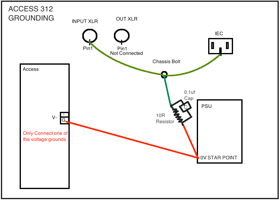
Yes it's plain wrong, there's no reason to have that many 0V connections. Only one is needed and only one should be connected, having 3 it's just confusing for people and also all the grounding docs in this thread are wrong, even if it works it's theoretically wrong.
The Star Point in grounding is not the Bolt case but the 0V point where all the Access preamp PCB will connect on the PSU.
From the Star Point, only 1 connection is made to the Chassis Bolt through a 10R resistor and one 0.1uf capacitor in parallel.
Input XLR pin1 is connect directly to the chassis bolt
Output XLR pin1 is not connected, just leave it open, the shielding will be connected to ground at the input on the next box that is connected in the chain.
A recommended reading:
Grounding and Shielding Audio Devices
http://www.rane.com/note151.html


")