Access-312 Build Thread

GroupDIY Audio Forum

Help Support GroupDIY Audio Forum:

This site may earn a commission from merchant affiliate links, including eBay, Amazon, and others.
  • Finally done boys. Lol wired the pots backwards so gotta wire em the other way. I have a whistlerockaudio.com passive di I built based off the schematic with a little help from 3nity I was able to cut a trace on the board and wire up the di to a switch I also have an impedance switch I plan on putting purple leds for the phantom. Need to rotate the toroidal for less noise on the last channel but I can see the light it sounds beautiful btw.
 

Attachments

  • 1463211277219.jpg
    1463211277219.jpg
    967.2 KB
Here's the front panel have to rewire pots so didn't put the knobs on yet
 

Attachments

  • 1463211411540.jpg
    1463211411540.jpg
    720.7 KB
Hello, can anyone shead some light on pin 2 and pin 3 on the layover and the board it self? was this updated at some point? it seems pin 2 and 3 on the inputs are different.  thanks for some great cards
 

Attachments

  • access 312.JPG
    access 312.JPG
    166.1 KB
here's the layover

http://twin-x.com/groupdiy/albums/userpics/312-Layout_.pdf
 

Attachments

  • access layover.pdf
    83.7 KB
dude24man said:
Hello, can anyone shead some light on pin 2 and pin 3 on the layover and the board it self? was this updated at some point? it seems pin 2 and 3 on the inputs are different.  thanks for some great cards

Hi guess it was a typo on that layout pdf, but it's easy to clear it up.

So XLR Pin2 is the + SIGNAL , XLR Pin3 it's the - Signal

1) Install/Solder the 3 switches (phase, pad, 48V) have all them in off position
2) Solder or install jumper from 1-2 and 3-4 for the input transformer  (primaries in parellel)
3)Measure continuity between the XLR Pin2 Pad on the PCB and  Pin 1 and 2 on the input transformer
4)Measure continuity between the XLR Pin3 Pad on the PCB and  Pin 3 and 4 on the input transformer

If you have continuity in  steps 3) and 4) then the silkscreen on your PCB is correct and the layout on the pdf is wrong


Measured continuity from pad 2 to pin 1, I got 38 ohms
Measured continuity from pad 3 to pin 4, I got 38 ohms

this is with the switches and all resistors installed.
 
One last problem I'm having with the phaton power led, when I install a led on the 2 switch legs I'm not getting the led to light up. any ideas would be great aswell. here's a picture so far
 

Attachments

  • access right pic.JPG
    access right pic.JPG
    147.1 KB
dude24man said:
One last problem I'm having with the phaton power led, when I install a led on the 2 switch legs I'm not getting the led to light up. any ideas would be great aswell.

Turn Phantom Power on, then:

1) Measure DC voltage between INPUT XLR Pin2 and Pin1.
2) Measure DC voltage between INPUT XLR Pin3 and Pin1.

Do you measure 48V on step 1 and setp 2?

if  the answer is yes, then:

Are you installing the Led with the correct leg orientation?


Whoops, Thanks a bunch for all your help. I got 48v on pins 2 and3. I was touching the wrong legs of the switch with the led. all is work fine now. Arthur
 
Hi all,

I'm going to build 4 2503 output txf for this 312 preamp as I've built 4 units in  a 1U rack.
I'm using sowter input txf.
I am a little confused with winding the secondary's as in the attached diagram is shows the secondary's connected together but then another winding for monitor amp output.
Is the winding just another separate winding which is the same as one of the other windings or a winding which is the same as both windings in series?

I would also like to put in the instrument input.

The plan is to wind the output txf with 1 X 166 turns pri, 1 X 300 sec, 1 X 166 pri, 1 X 300 sec, 1 X 166 Pri
Then connected up all primary's and secondary's , I'm using 0.25mm diameter wire.

So should i do another winding of 500 turns for the monitor amp output?

Regards

Spence.
 

Attachments

  • API 312 DI mod..jpg
    API 312 DI mod..jpg
    196.2 KB
Spencerleehorton said:
I am a little confused with winding the secondary's as in the attached diagram is shows the secondary's connected together but then another winding for monitor amp output.
Is the winding just another separate winding which is the same as one of the other windings or a winding which is the same as both windings in series?

It's  just another separate winding which is the same as one of the other windings, it's an isolated unbalanced output to feed a monitor amp  or a VU meter
 
Just out of curiosity, why is there so many ground connection on the board? I mean, I run a continuity test with all 3 ground connection on the board and they are all connected via an ground plane Under the board. So, theorically, we should have only one of them connected to the psu ground, then to the main bolt, not all 3 of them. Don't we run into chances of an ground loop by connecting the same ground 3 times to the main bolt (aka star ground) ??
 
Deepdark said:
Just out of curiosity, why is there so many ground connection on the board? I mean, I run a continuity test with all 3 ground connection on the board and they are all connected via an ground plane Under the board. So, theorically, we should have only one of them connected to the psu ground, then to the main bolt, not all 3 of them. Don't we run into chances of an ground loop by connecting the same ground 3 times to the main bolt (aka star ground) ??

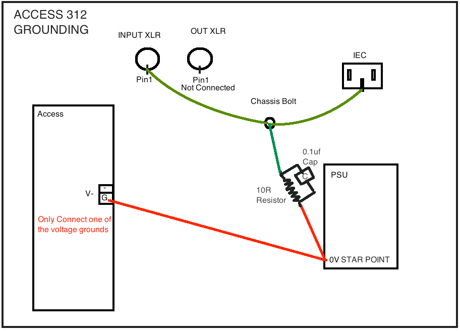
Yes it's plain wrong, there's no reason to have that many 0V connections. Only one is needed and only one should be connected, having 3 it's just confusing for people and also all the grounding docs in this thread are wrong, even if it works it's theoretically wrong.

The Star Point in grounding is not the Bolt case but the 0V point where all the Access preamp PCB will connect on the PSU.
From the Star Point, only 1 connection is made to the Chassis Bolt through a 10R resistor and one 0.1uf capacitor in parallel.
"It is used to stop ground loops happening. Isolates the chassis ground from the audio ground by 10R with 0.1uF across it so no RF gets in as well."

Input XLR pin1 is connect directly to the chassis bolt

Output XLR pin1 is not connected, just leave it open, the shielding will be connected to ground at the input on the next box that is connected in the chain.

A recommended reading:
Grounding and Shielding Audio Devices
http://www.rane.com/note151.html

GzDZvgd.png


Whoops said:
Deepdark said:
Just out of curiosity, why is there so many ground connection on the board? I mean, I run a continuity test with all 3 ground connection on the board and they are all connected via an ground plane Under the board. So, theorically, we should have only one of them connected to the psu ground, then to the main bolt, not all 3 of them. Don't we run into chances of an ground loop by connecting the same ground 3 times to the main bolt (aka star ground) ??

Yes it's plain wrong, there's no reason to have that many 0V connections. Only one is needed and only one should be connected, having 3 it's just confusing for people and also all the grounding docs in this thread are wrong, even if it works it's theoretically wrong.

The Star Point in grounding is not the Bolt case but the 0V point where all the Access preamp PCB will connect on the PSU.
From the Star Point, only 1 connection is made to the Chassis Bolt through a 10R resistor and one 0.1uf capacitor in parallel.

Input XLR pin1 is connect directly to the chassis bolt

Output XLR pin1 is not connected, just leave it open, the shielding will be connected to ground at the input on the next box that is connected in the chain.

A recommended reading:
Grounding and Shielding Audio Devices
http://www.rane.com/note151.html

Access%20312%20correct%20grounding.png

Yeah, actually, I refer to Grounding 101 by forum member Ian Bell. You're right, The 312 board go to the psu ground connection, then to the star bolt (which is the main bolt, too). For the XLR's, I use the chassis to handle shield grounding, so my xlr's pin1 are strapped to each of their  chassis lug . I tend to separate shield ground and signal groundas much as possible. Curious about the resistor/cap in paralelle. What is the goal of it?

Here is my reference for grounding: http://www.ianbell.ukfsn.org/EzTubeMixer/docs/EzTubeMixer/SimpleMixer/grounding101v2.pdf
 
Deepdark said:
Curious about the resistor/cap in paralell. What is the goal of it?

All JLM PSU's have that connection between 0V and Chassis.

From Joe Malone:

I would like to ask you some technical questions,
what is reason for the 10ohm resistor and 0.1uf caps that are on the board that connect 0V on the PSU to Case ground?


It is used to stop ground loops happening. Isolates the chassis ground from the audio ground by 10R with 0.1uF across it so no RF gets in as well.
 
This is diy you can do whatever you want the way you want it too.

It was designed that way and proven to work thousands of times before...no one ever complained...i dont see why it bothers you..

I took the decisión to use 3 separate screw conectors merely based on my design goal..

And off course it was tested...
 

Latest posts

Back
Top