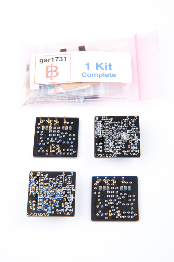
Since the kits have started shipping, it's time for the support thread! ")
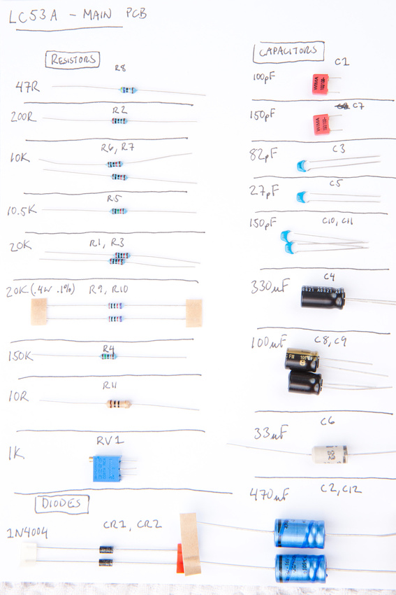
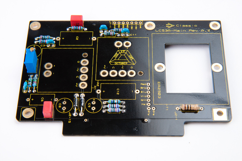
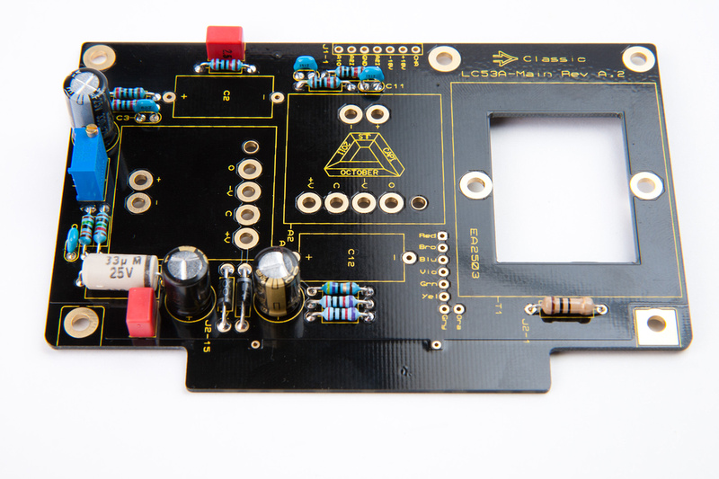
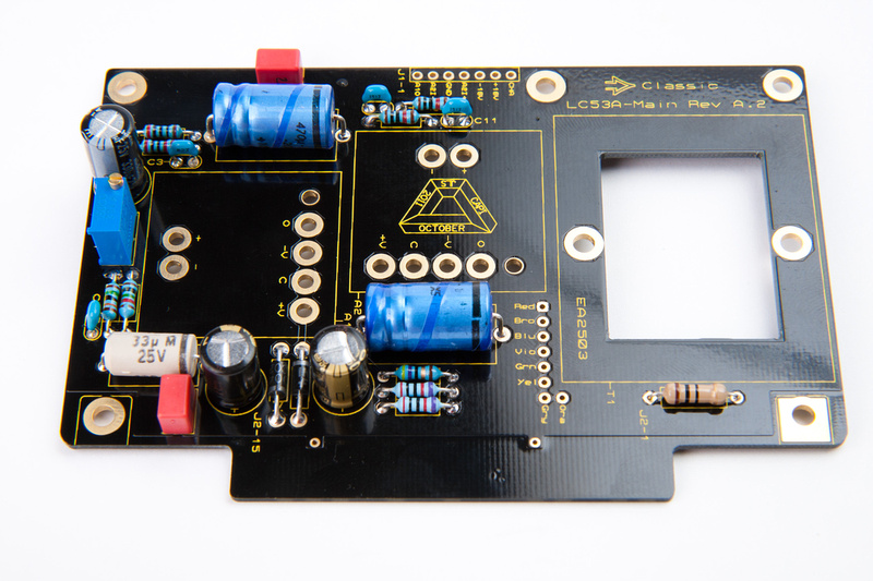
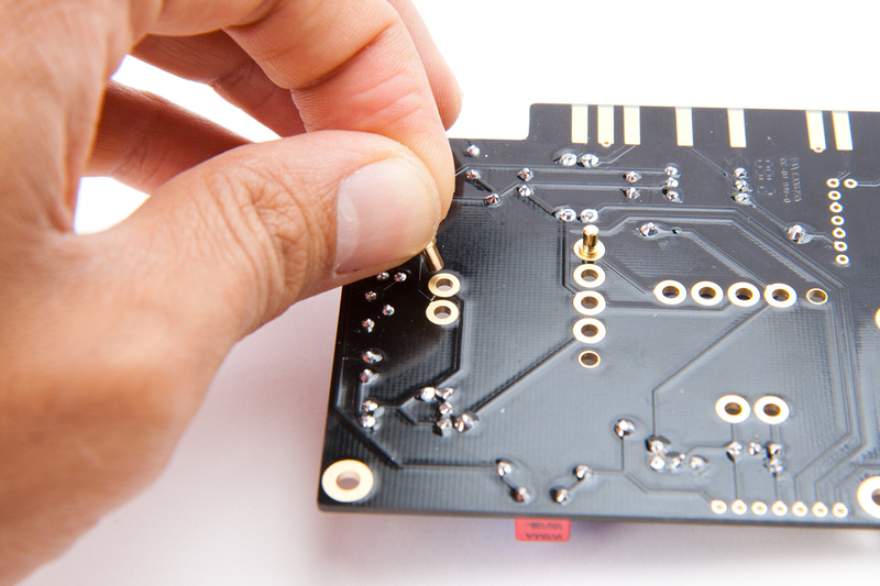
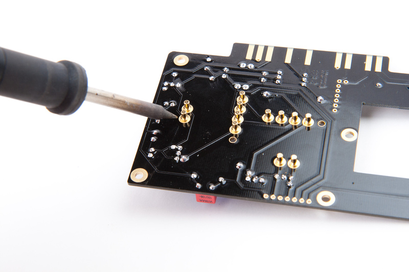
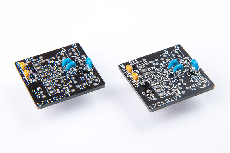
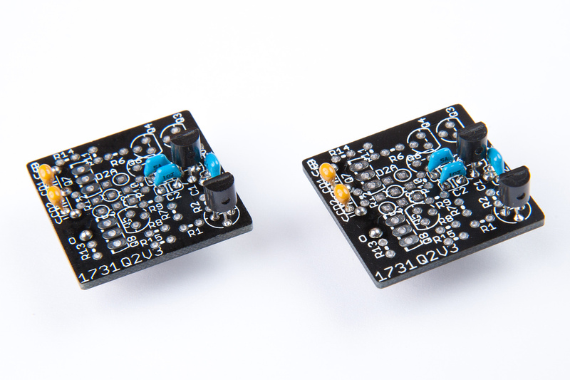
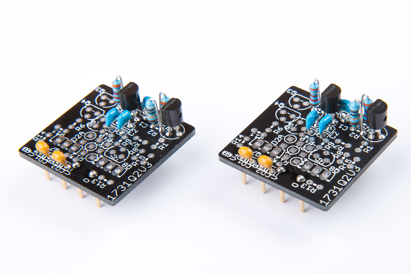
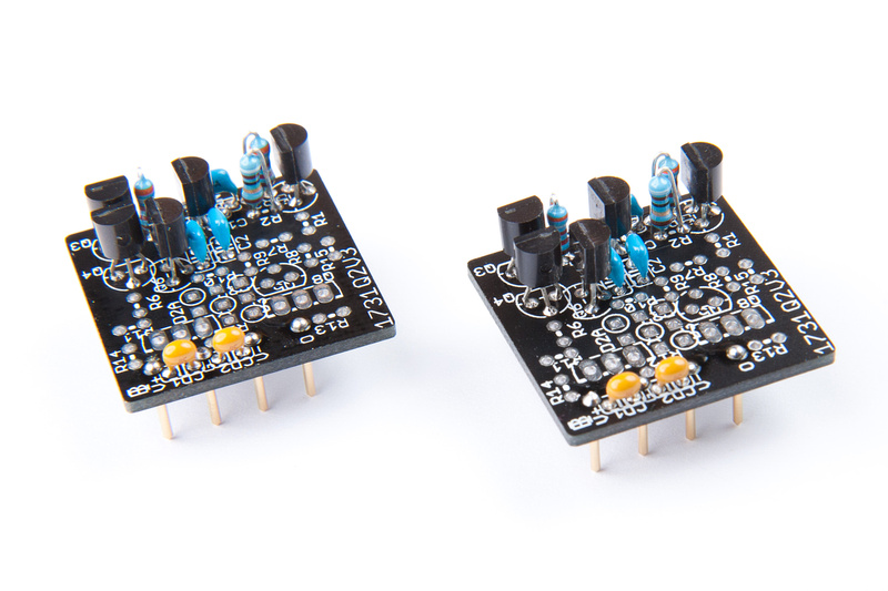
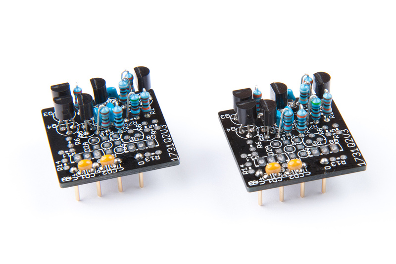
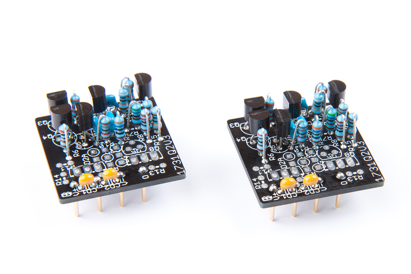
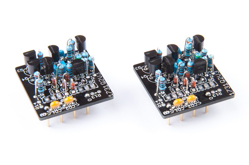
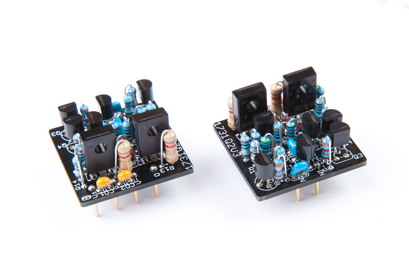
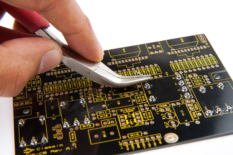
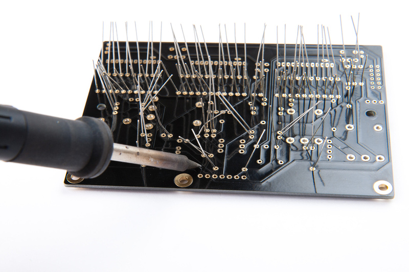
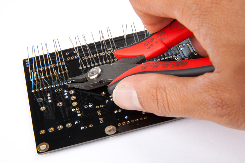
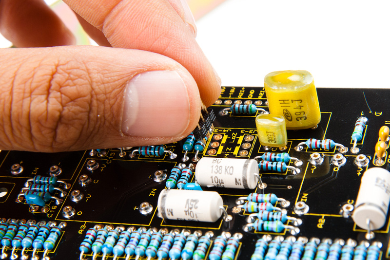
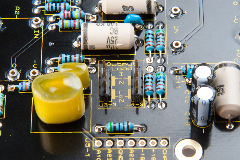
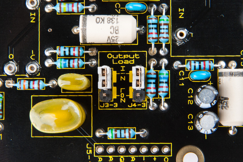
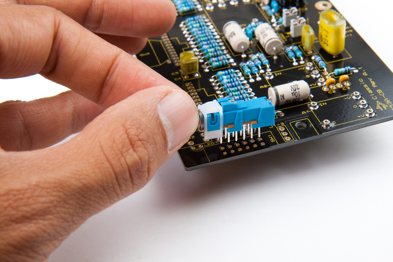
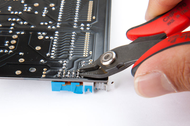
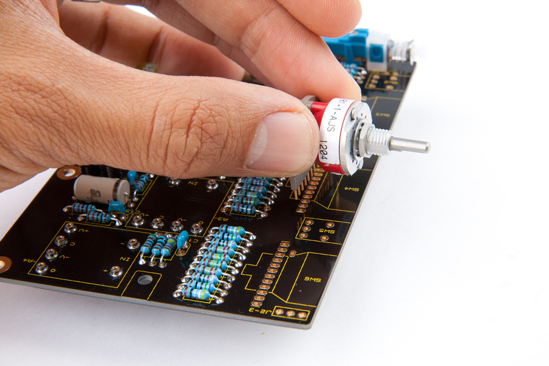
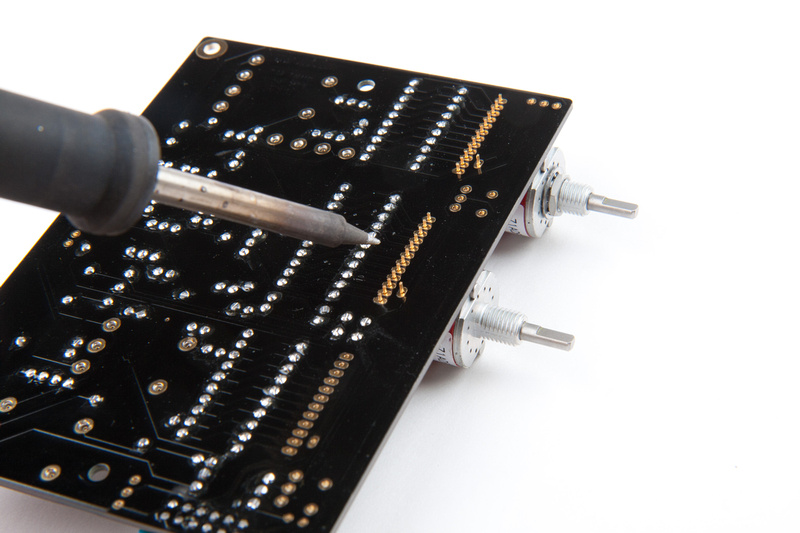
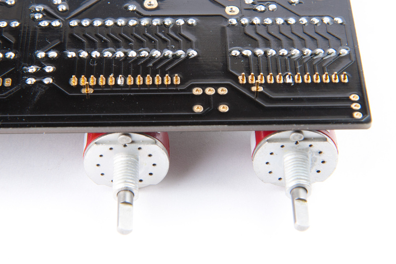
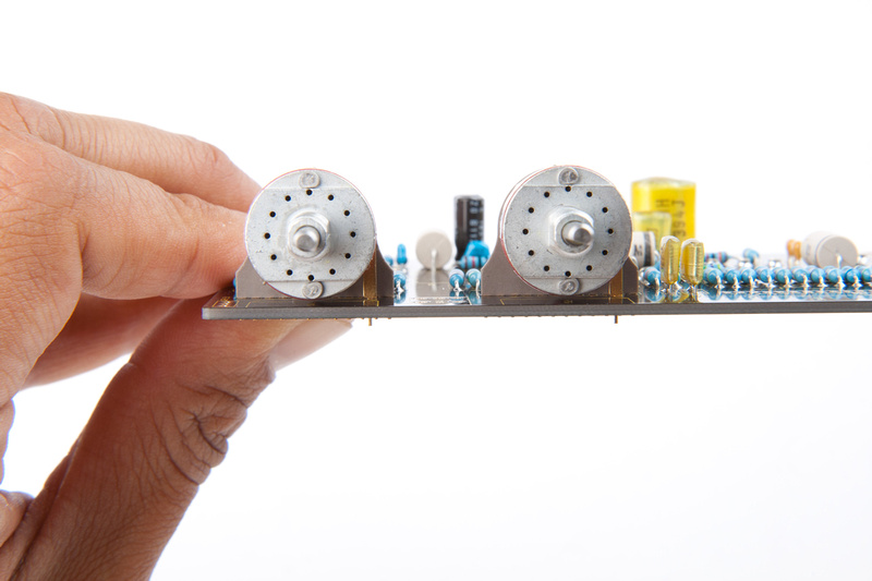
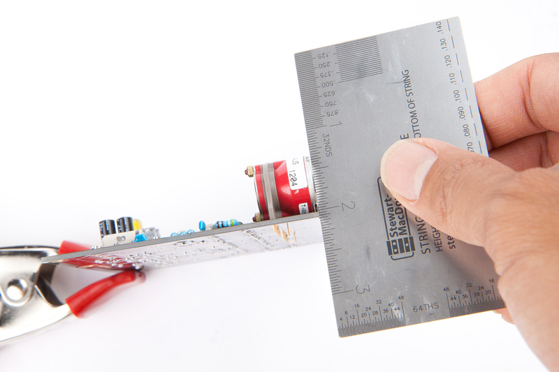
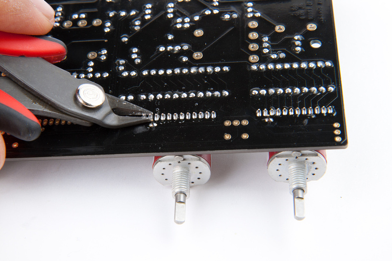
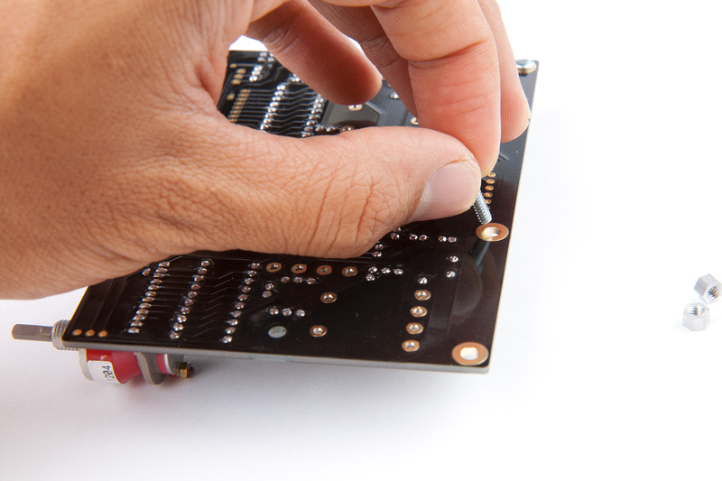
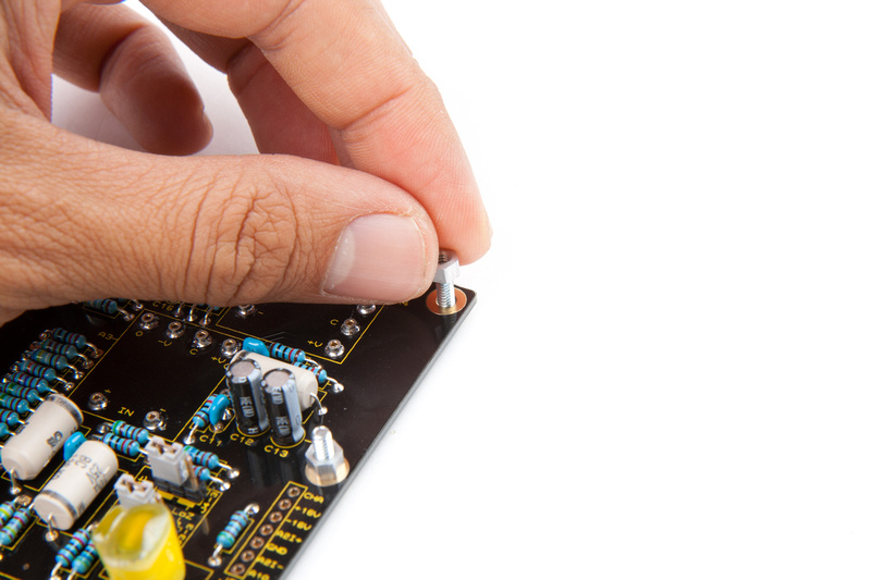
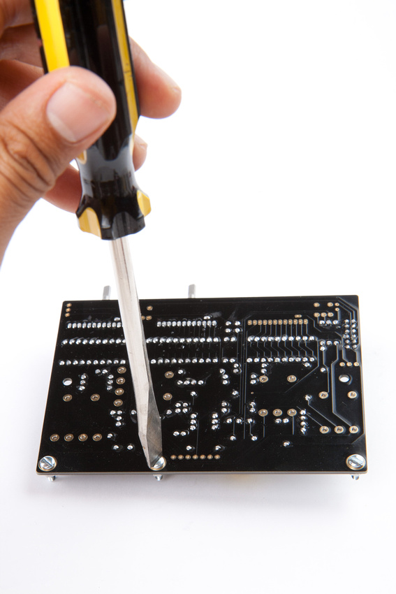
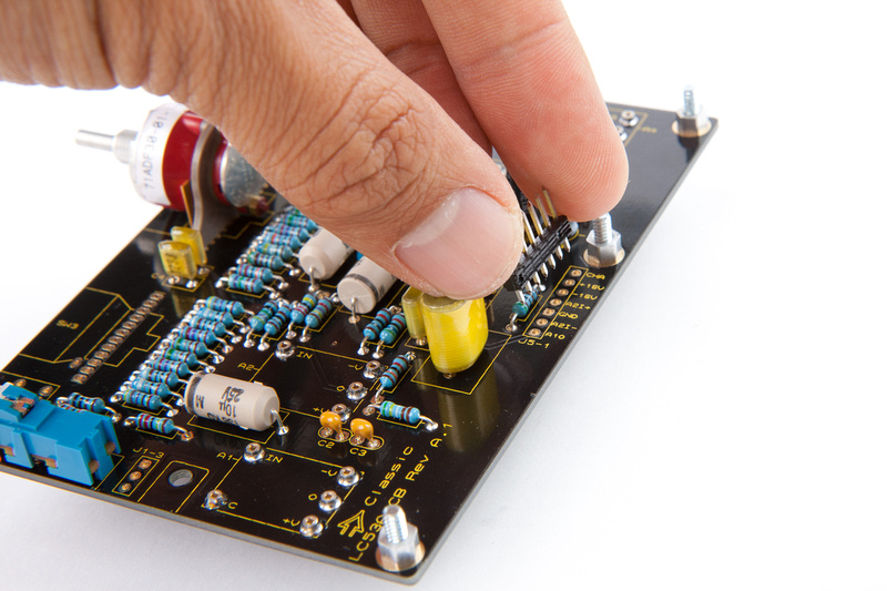
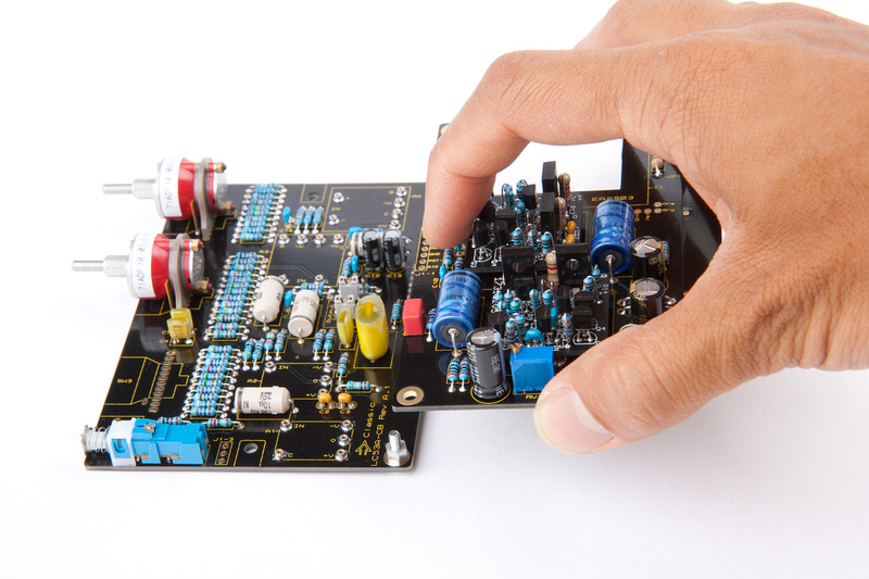
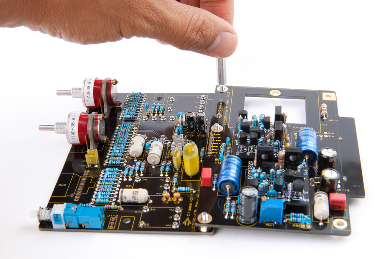
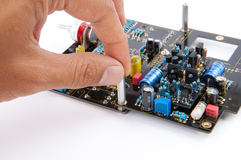
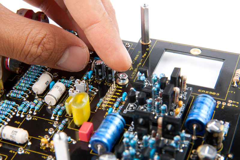
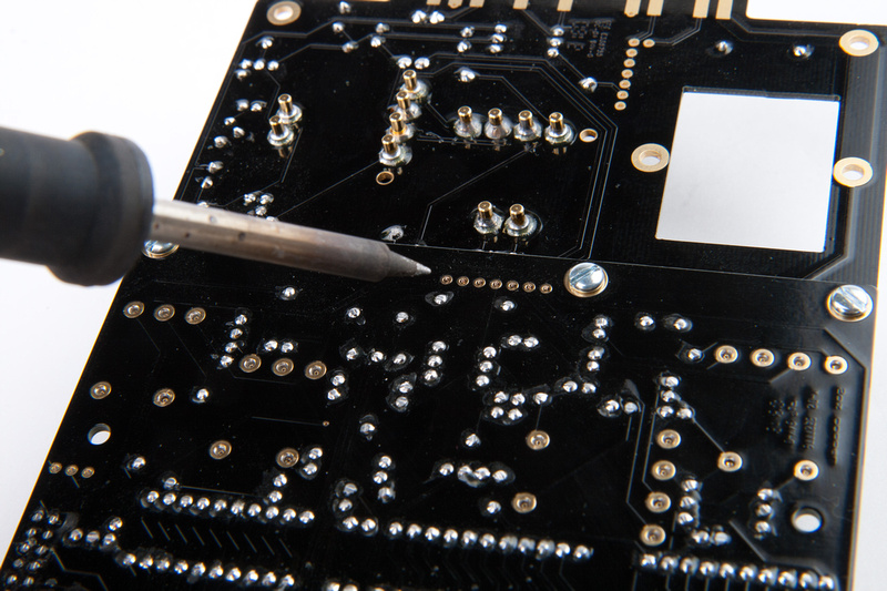
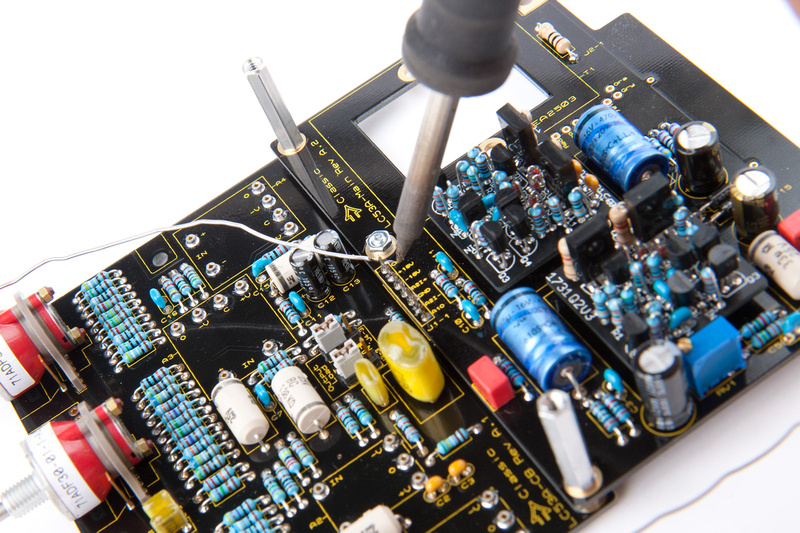
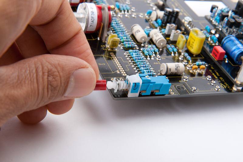
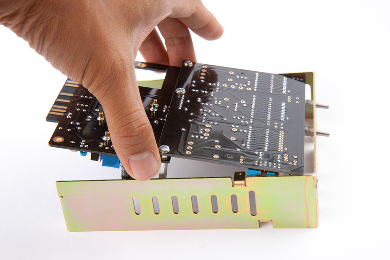
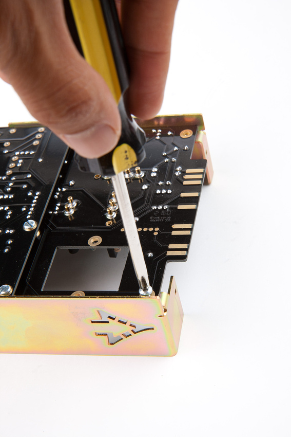
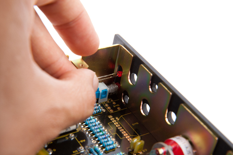
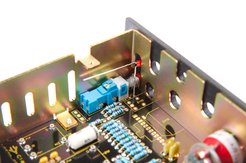
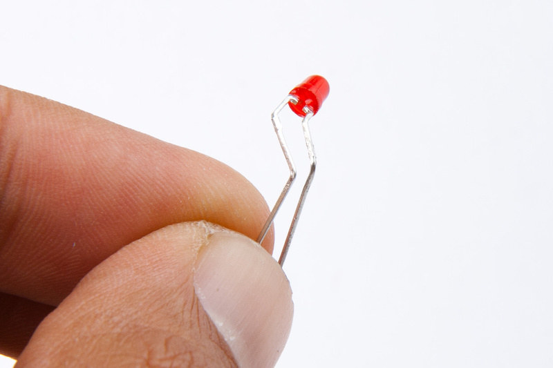
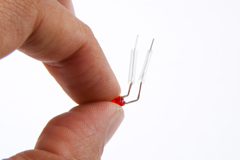
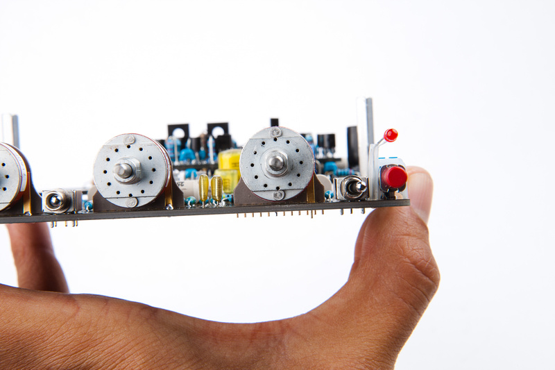
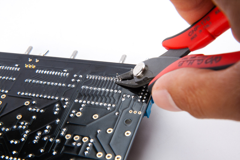
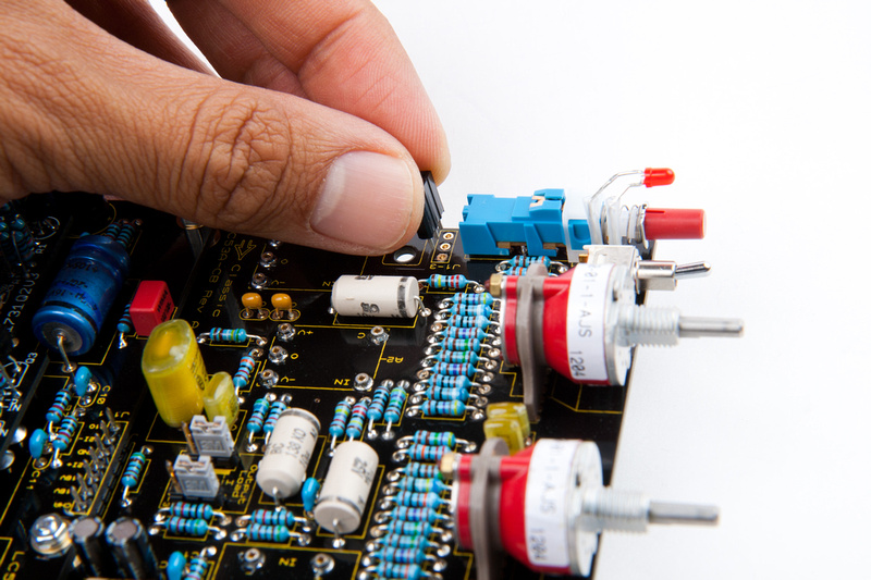
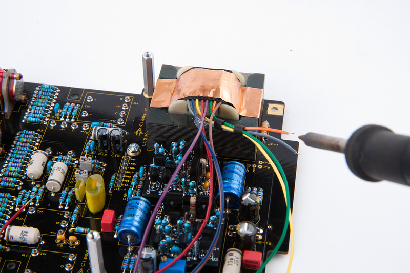
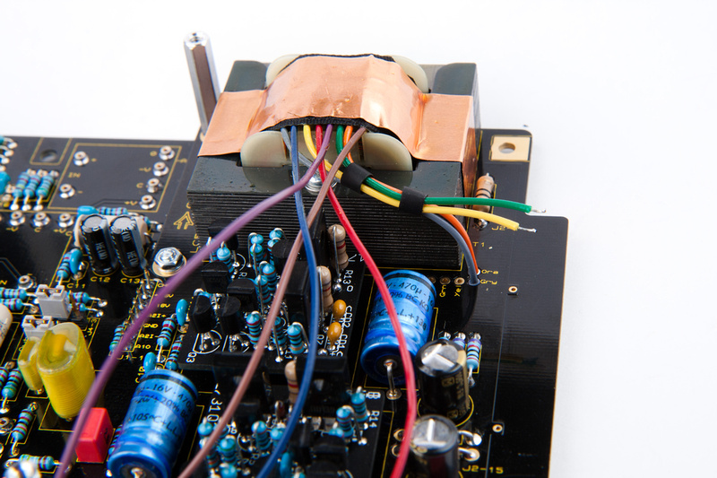
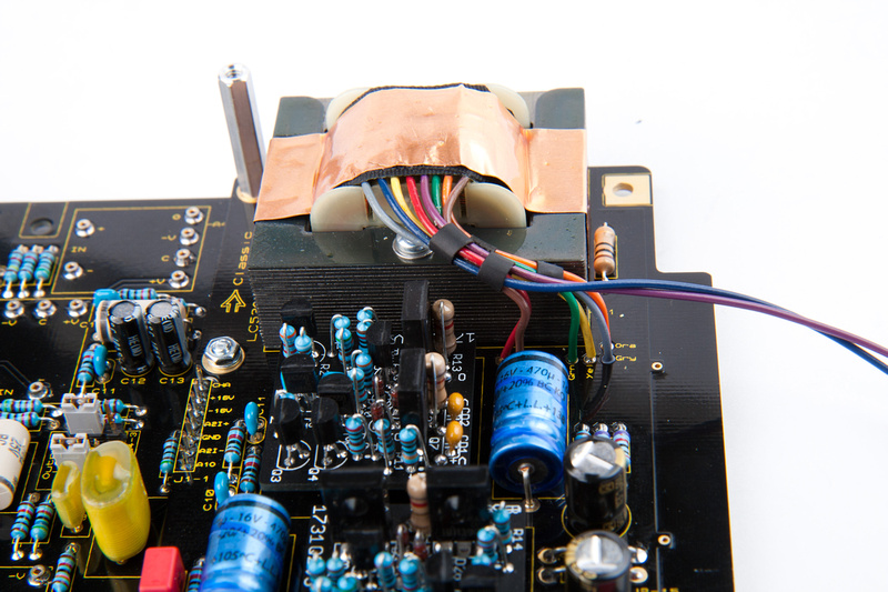
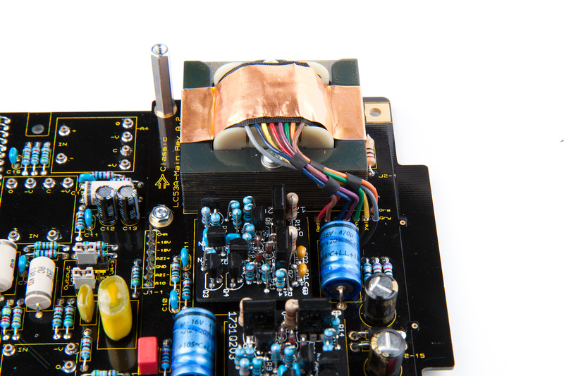
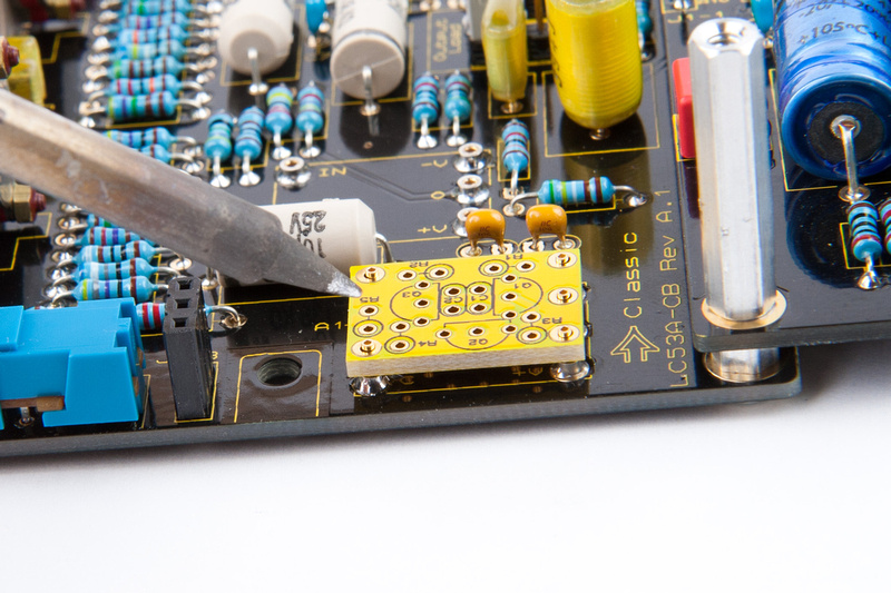
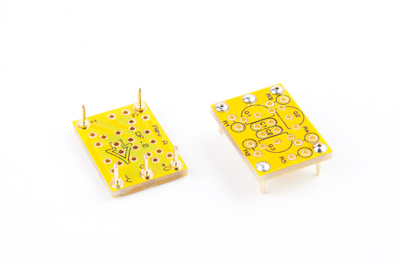
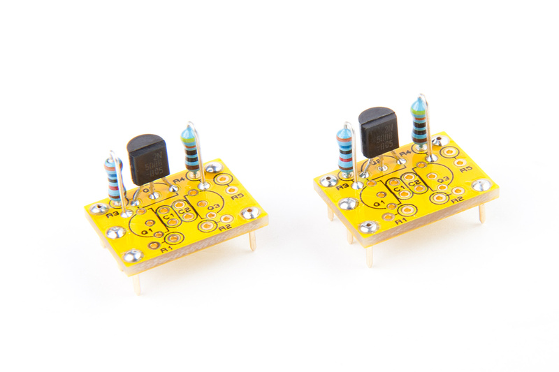
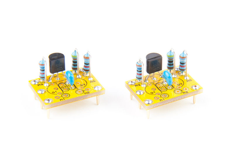
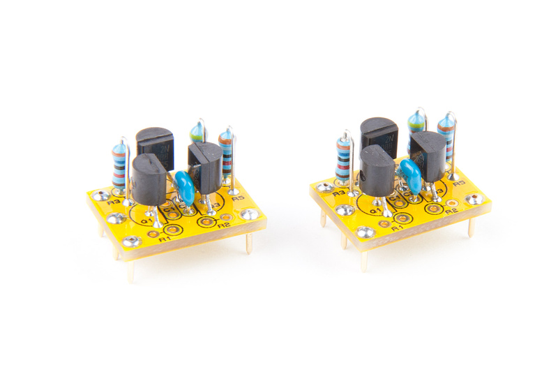
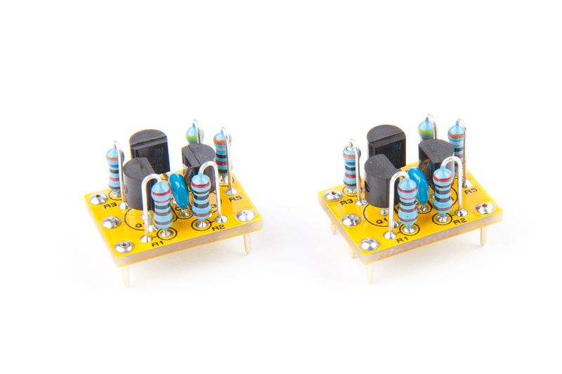
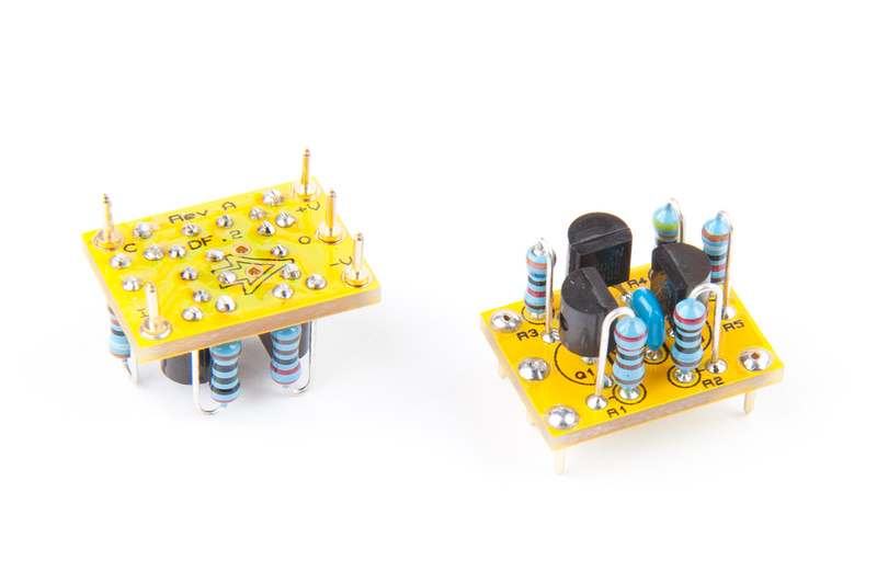
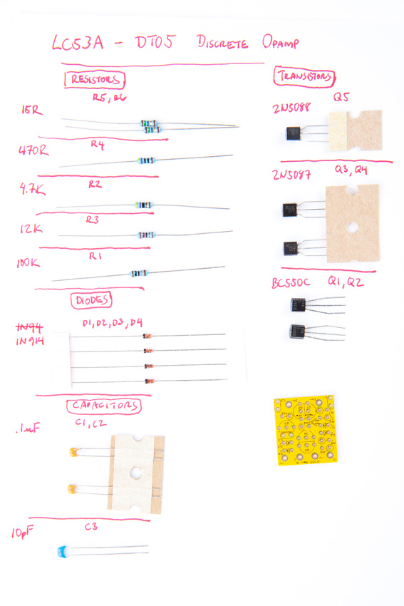
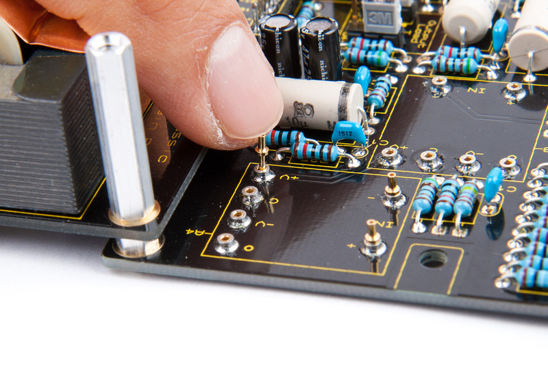
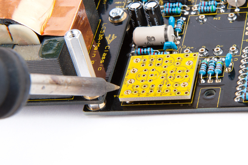
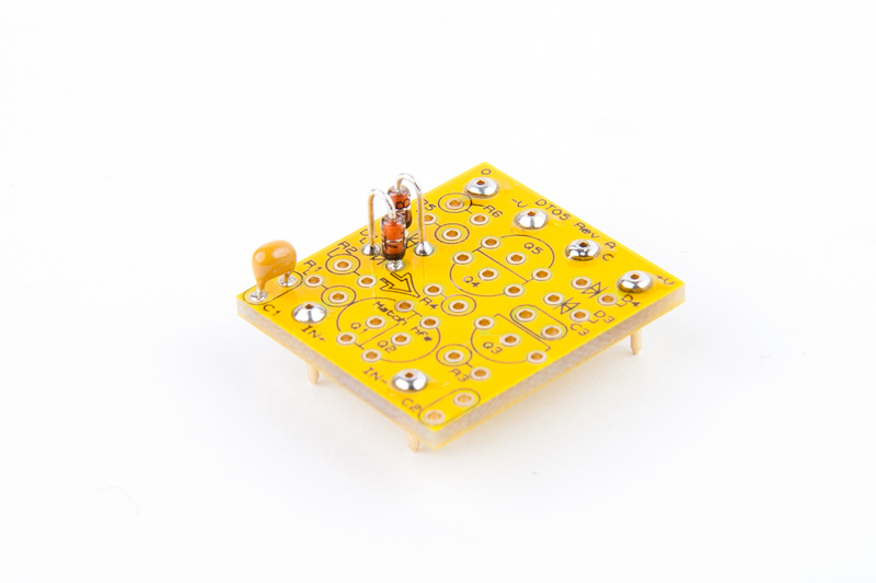
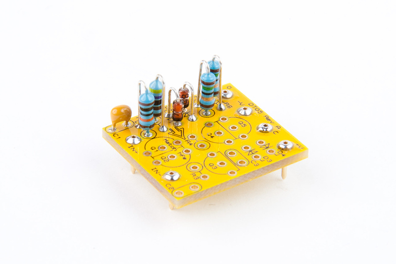
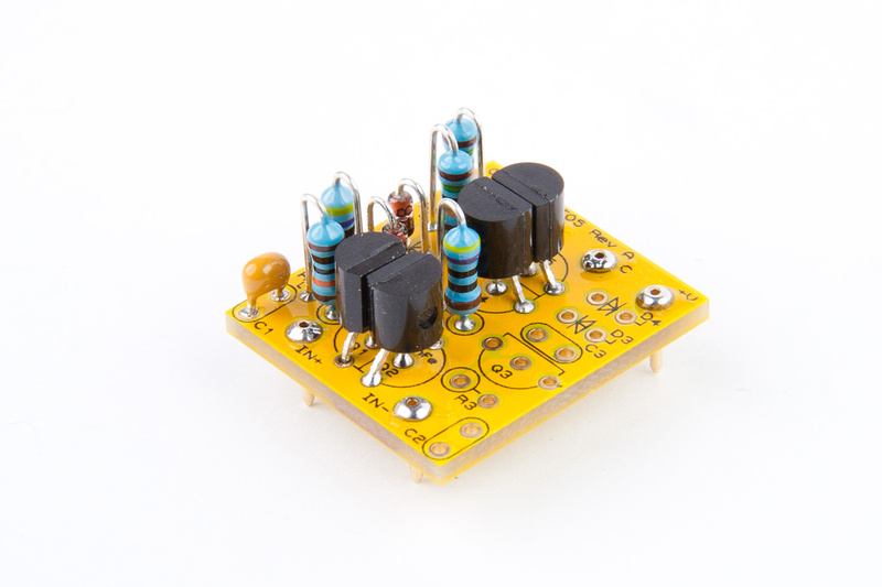
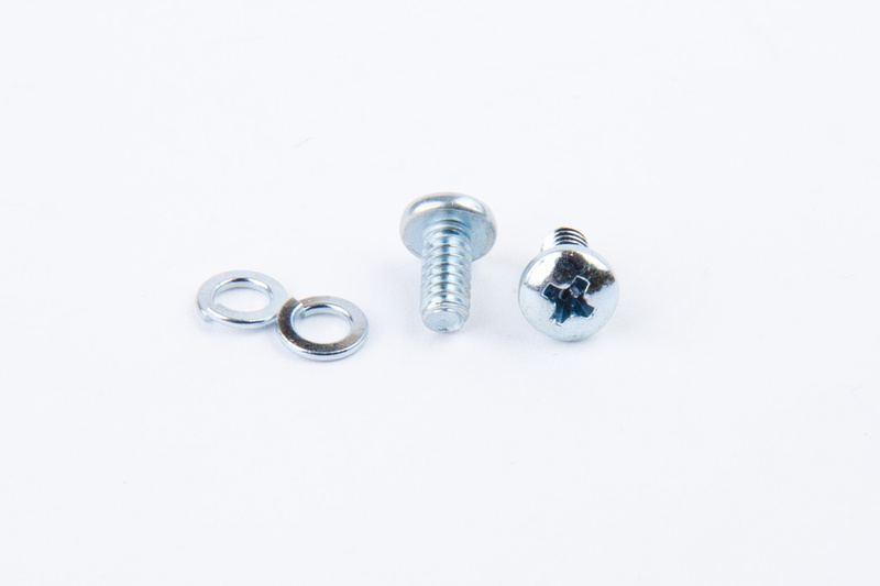
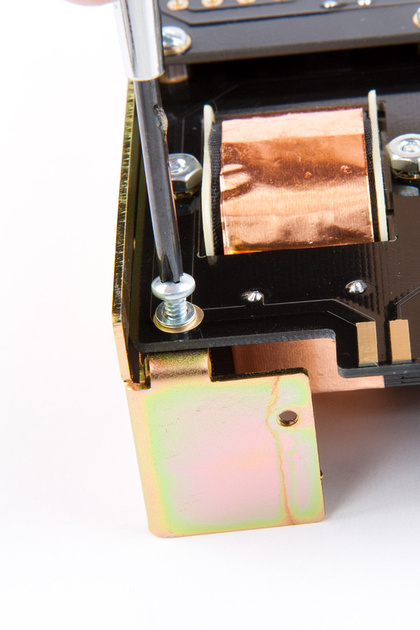
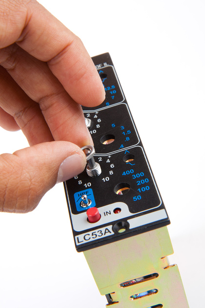
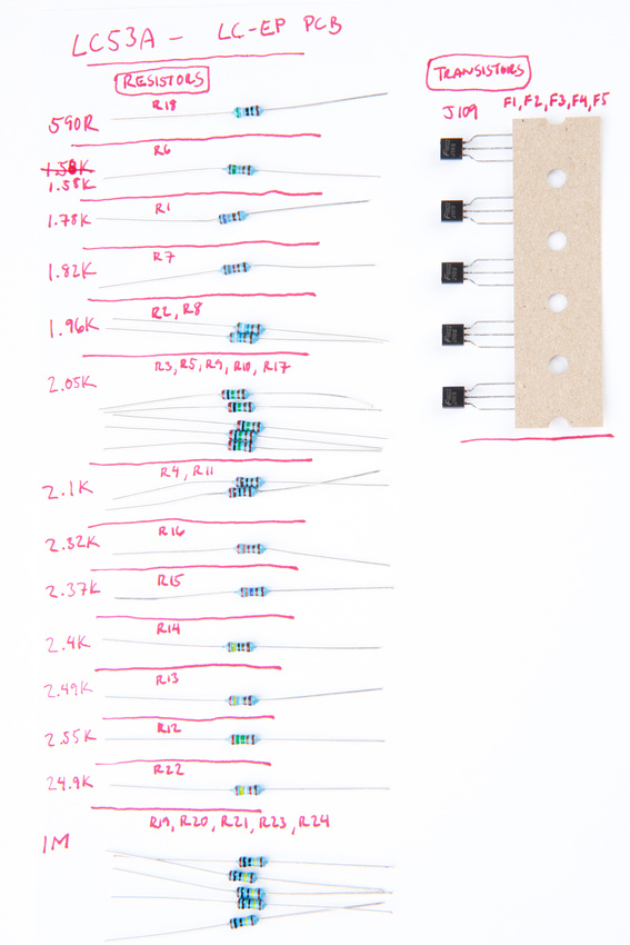
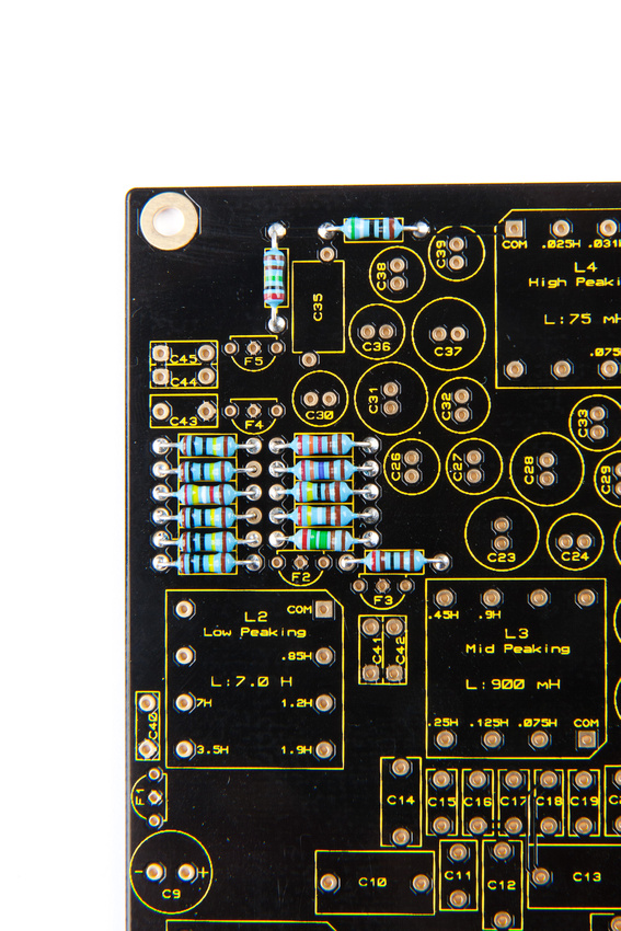
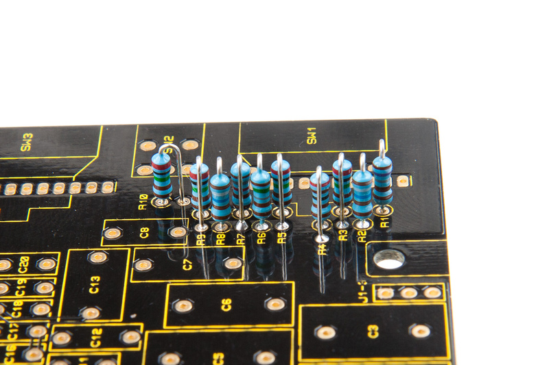
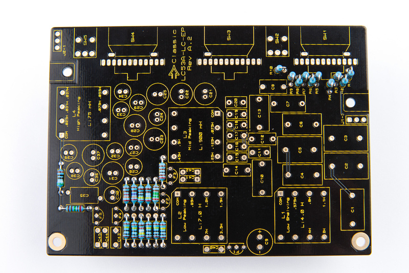
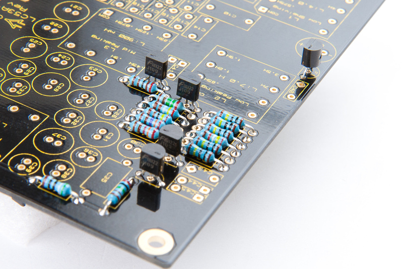
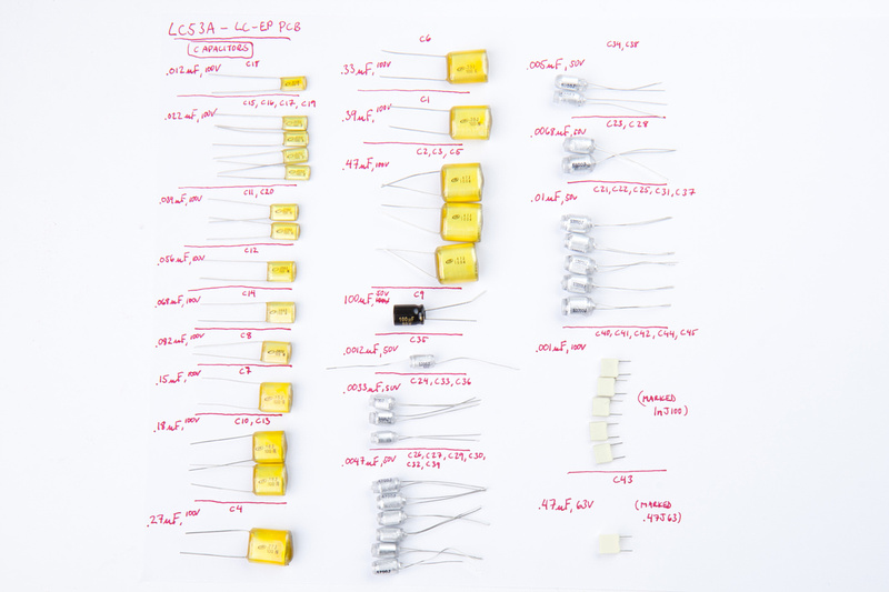
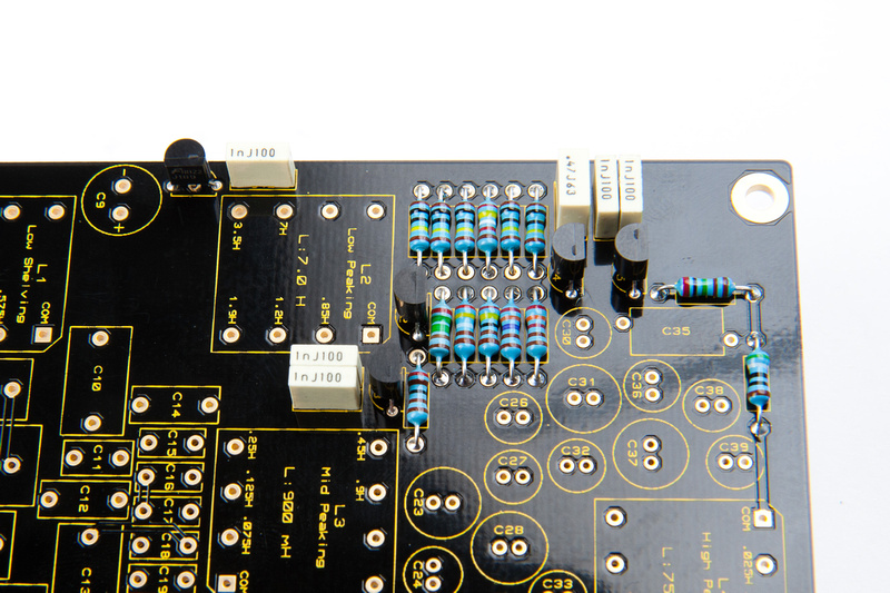
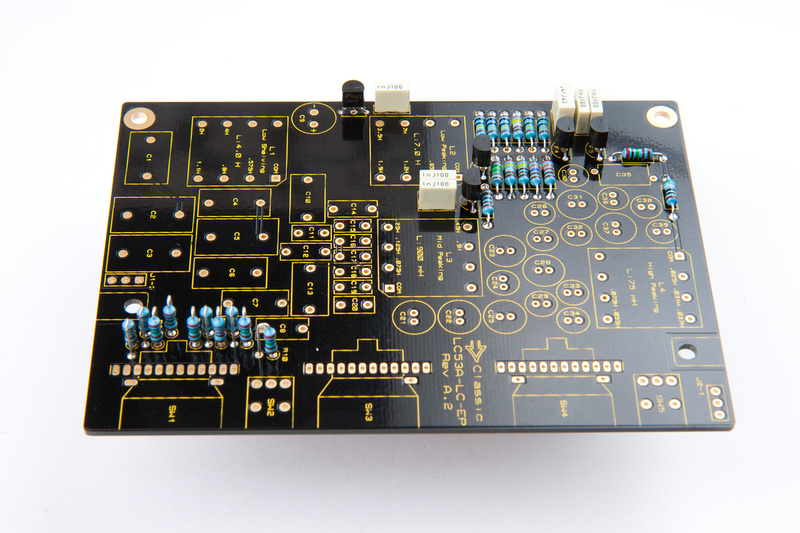
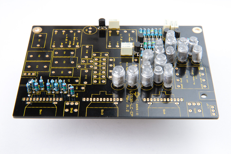
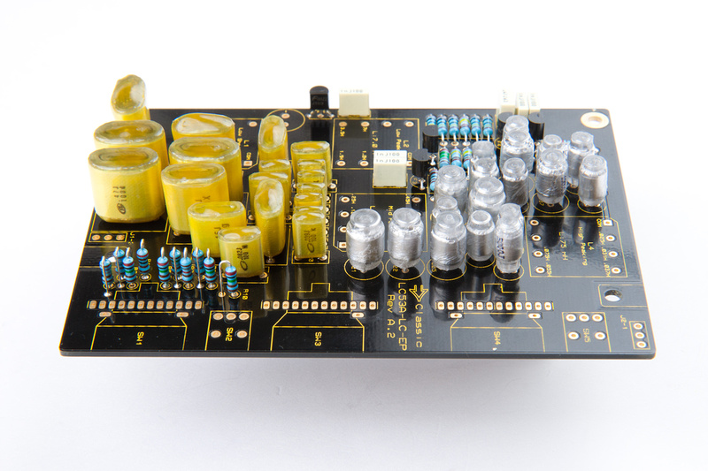
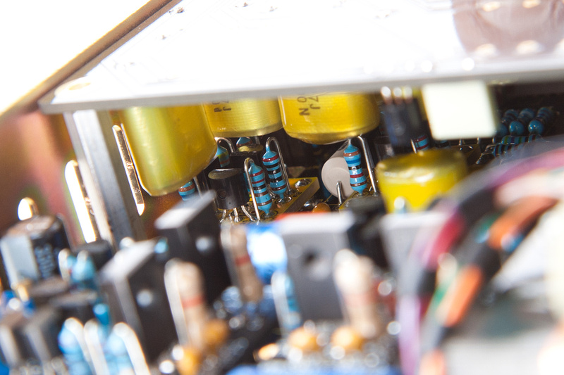
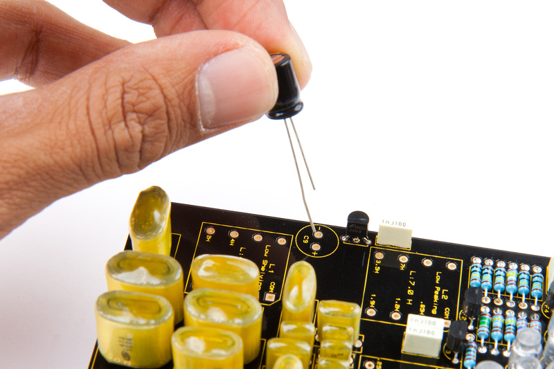
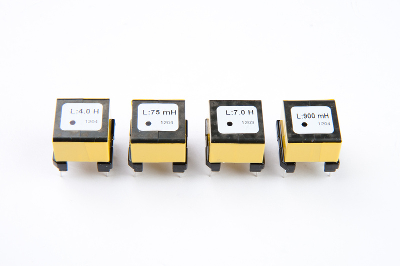
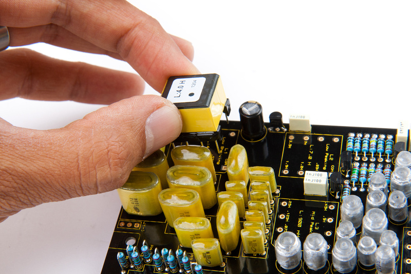
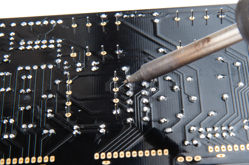
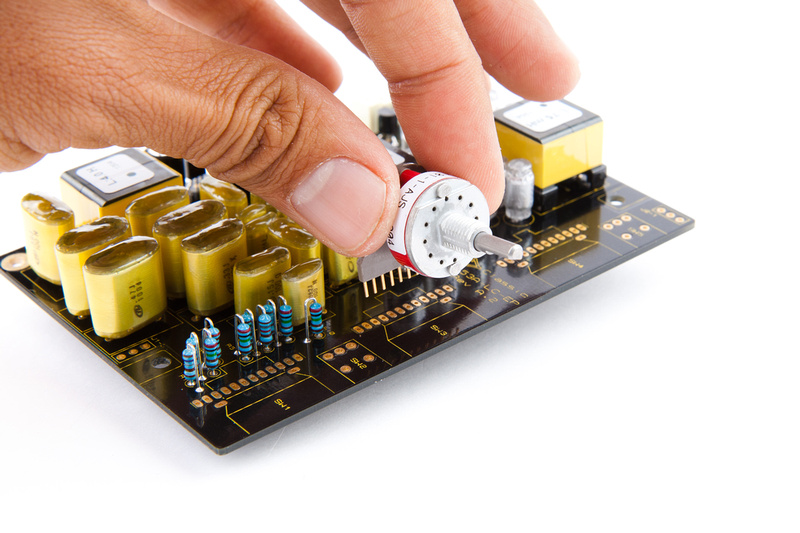
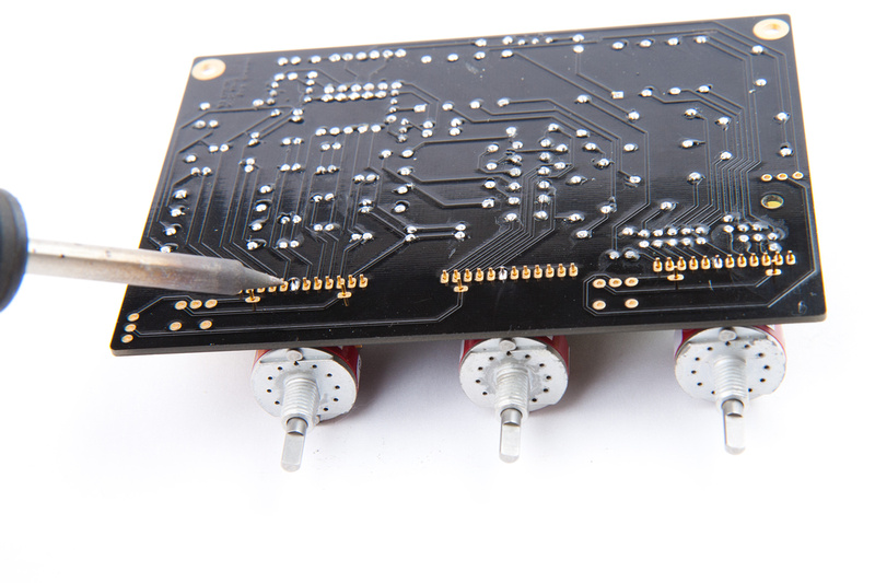
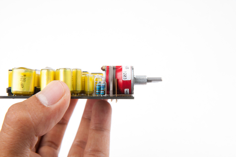
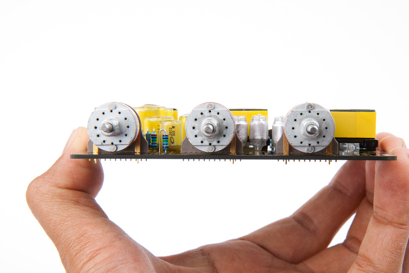
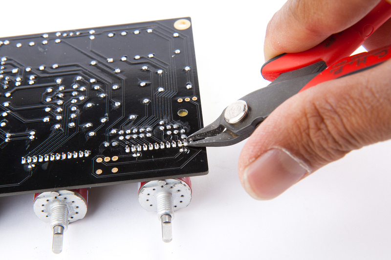
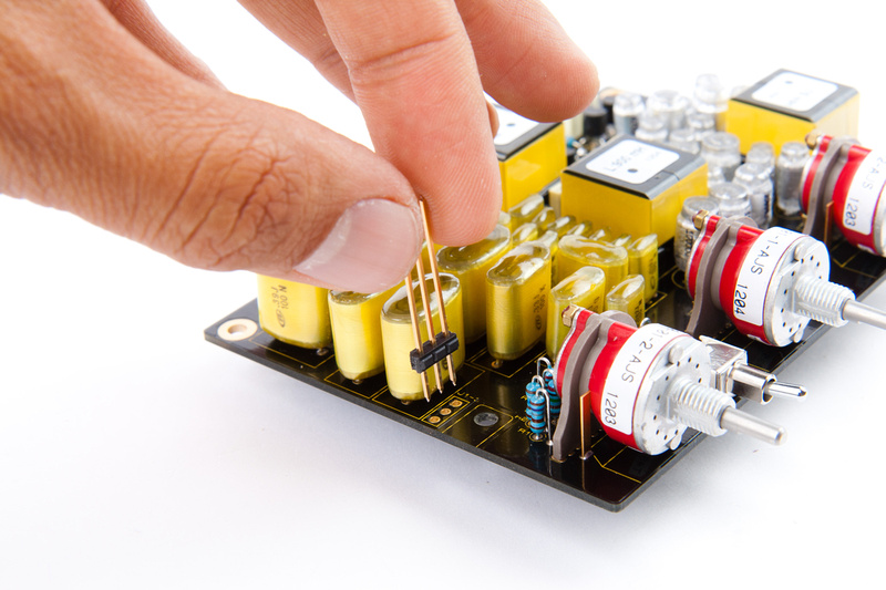
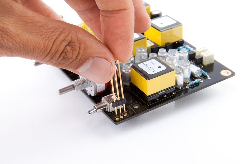
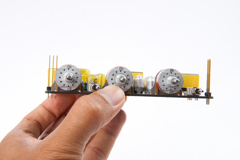
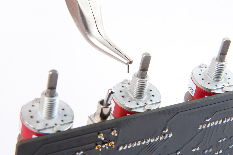
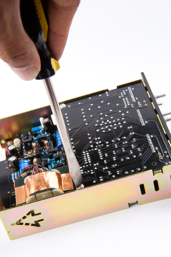
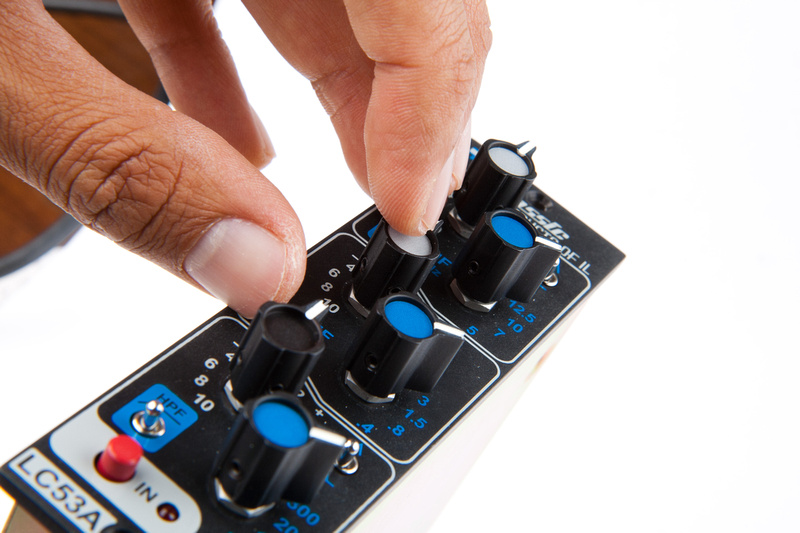
**This is a semi complicated build. It is very important to read completely thru the Assembly Aid before starting on anything. There are some points made in the doc that can save you much time and prevent crucial errors during the build.
--------------------------------------------------------------------------------------------------------
September 21st, 2015 Update:
All support docs for this project can be found on the recently added Support Docs page at www.capi-gear.com
--------------------------------------------------------------------------------------------------------
--------------------------------------------------------------------------------------------------------
March 5th, 2016 Update:
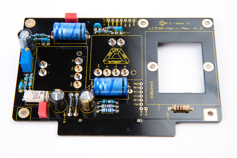
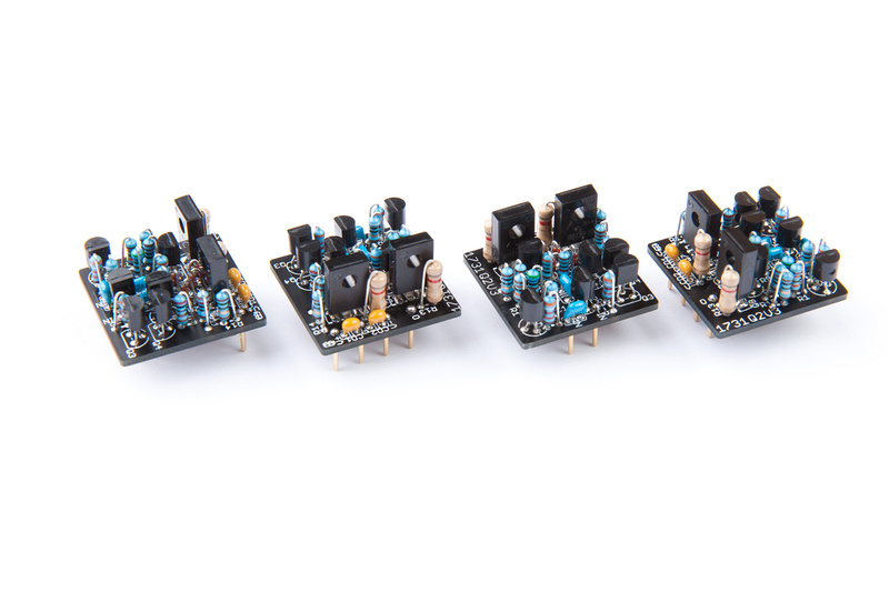
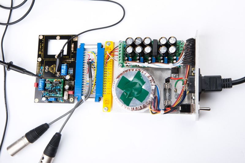
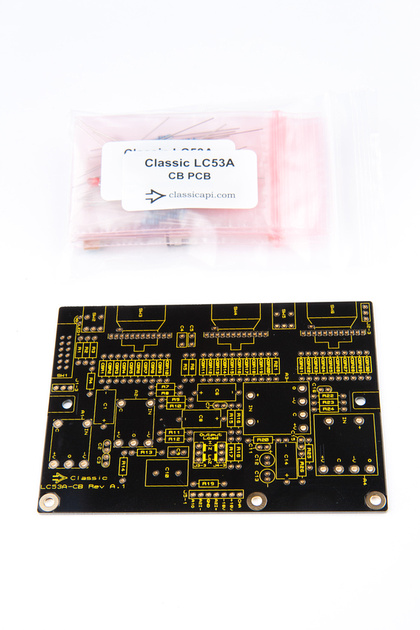
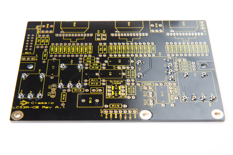
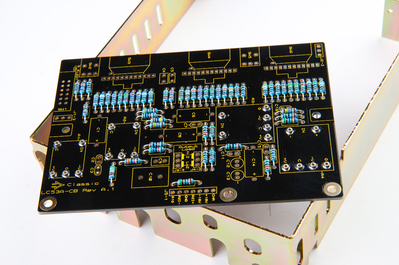
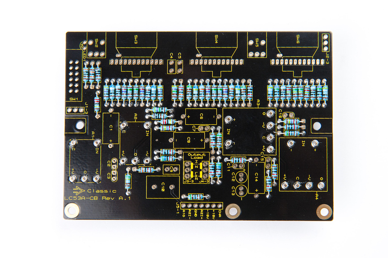
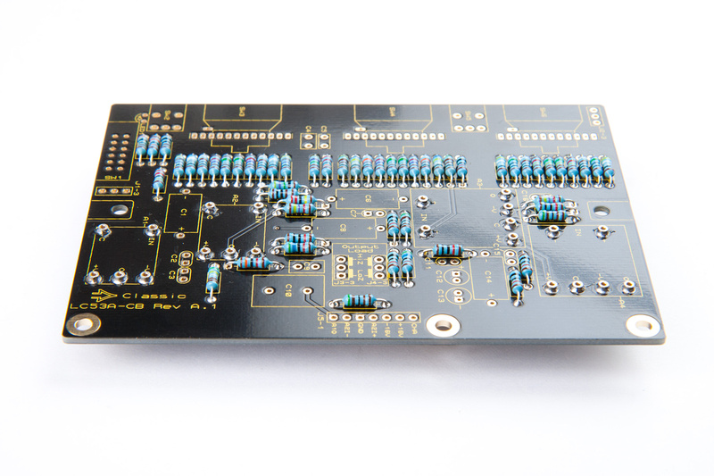
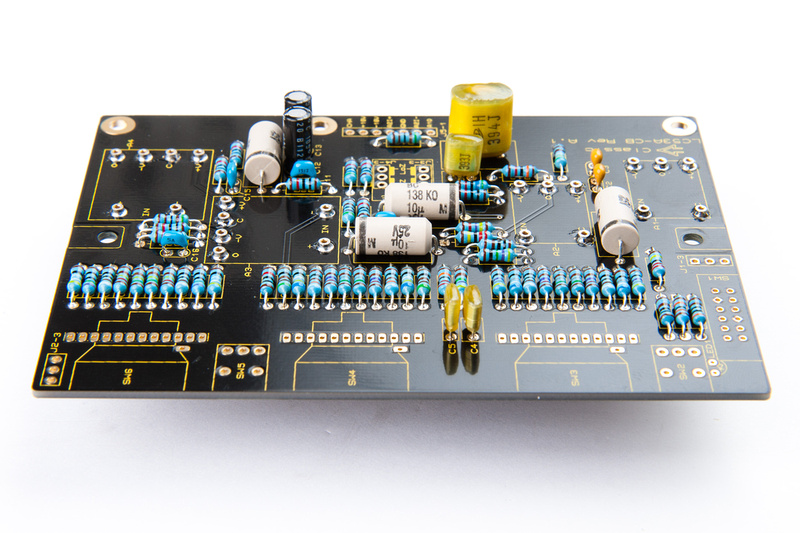
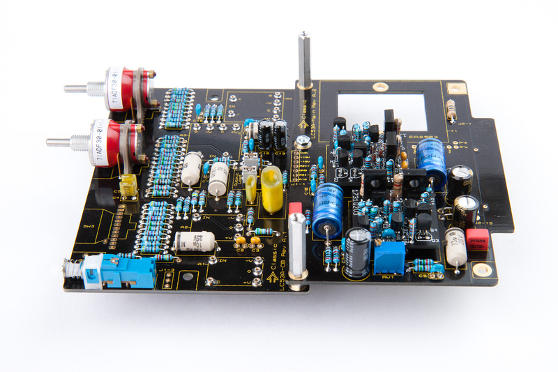
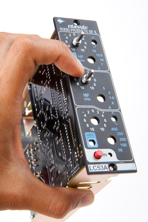
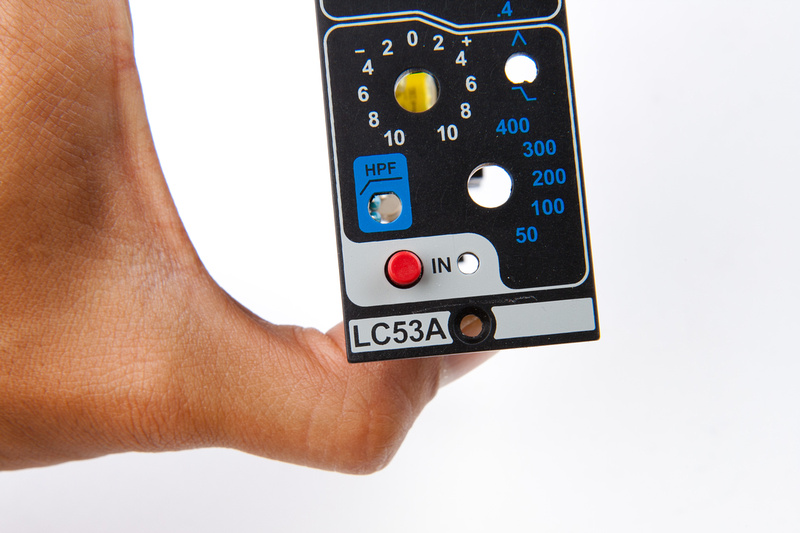
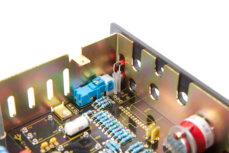
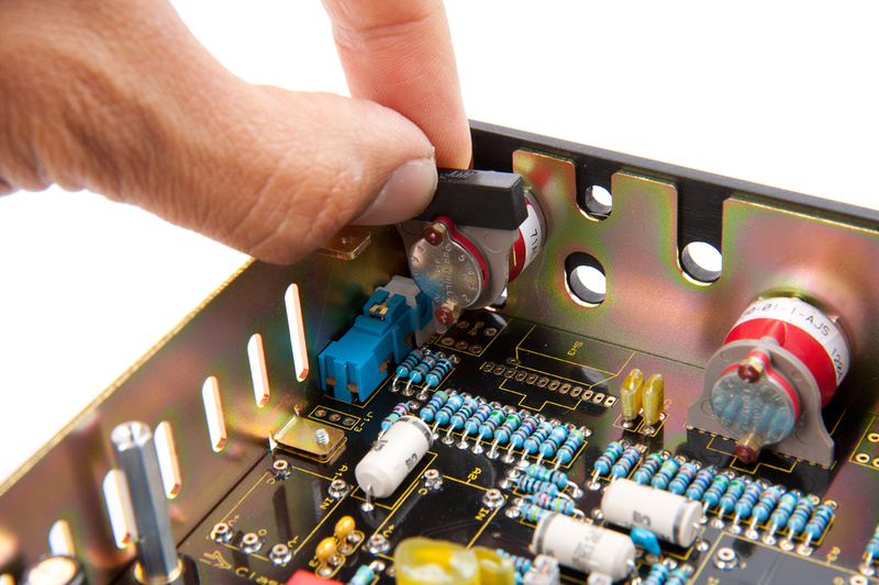
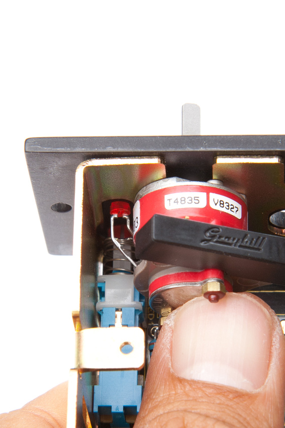
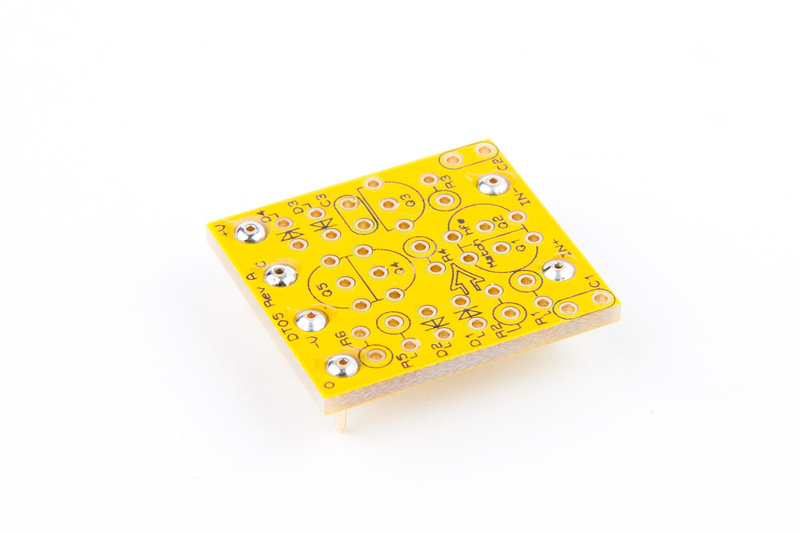
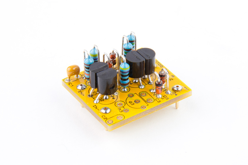
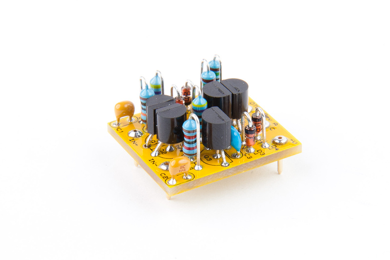
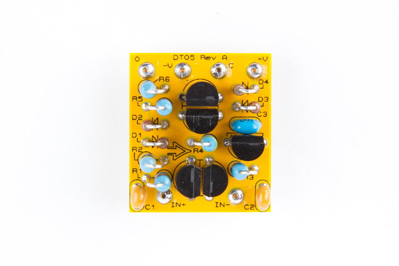
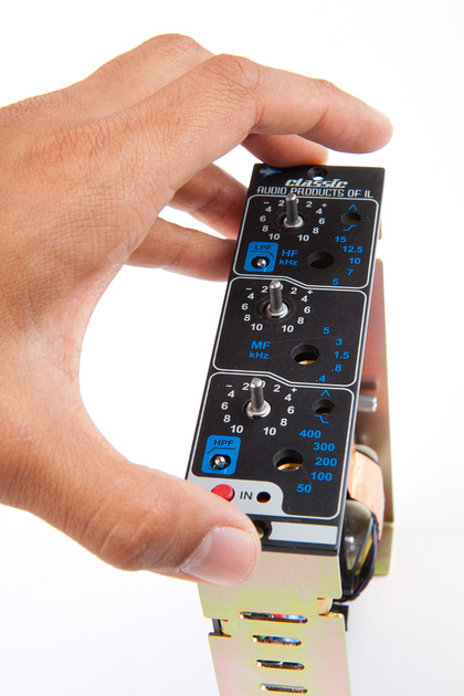
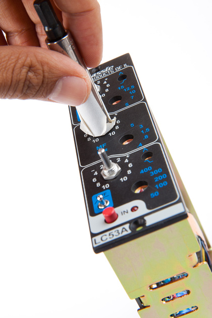
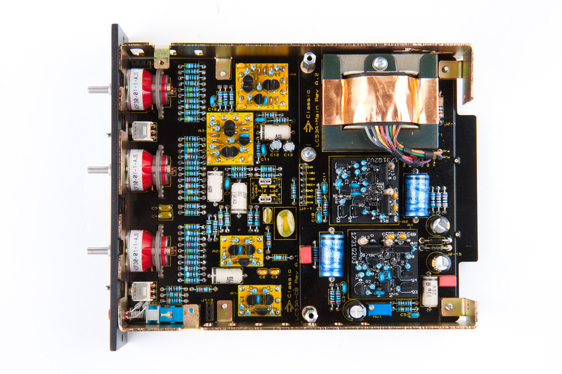
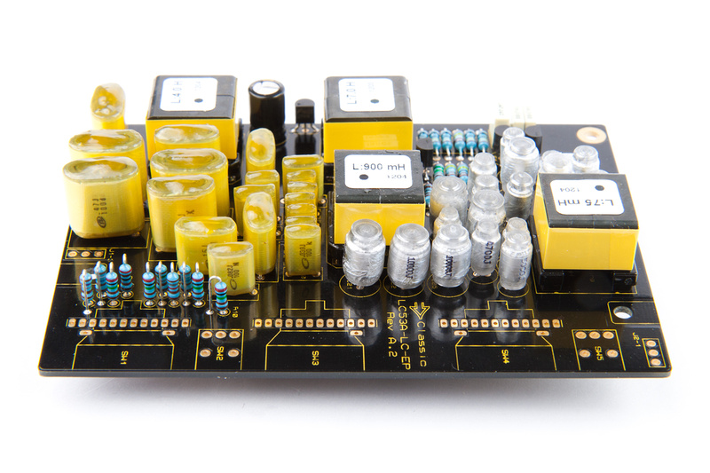
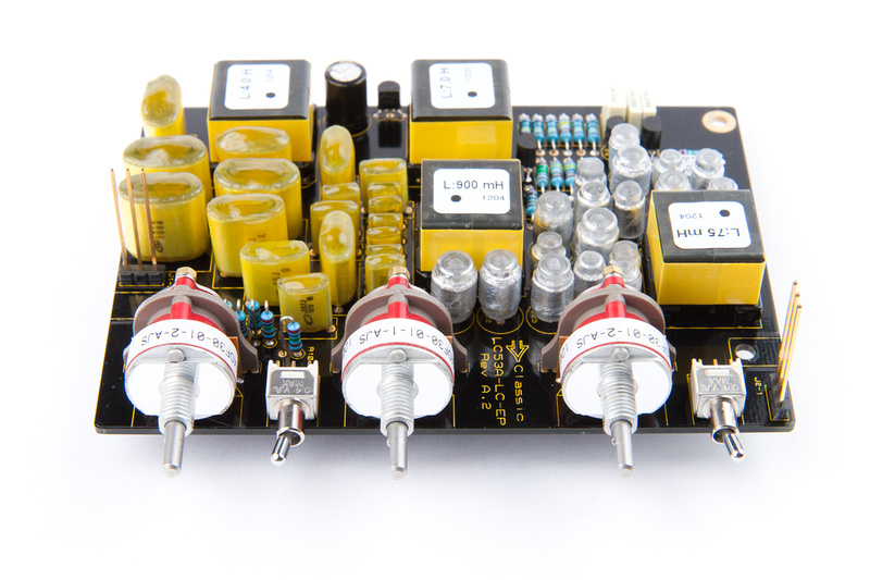
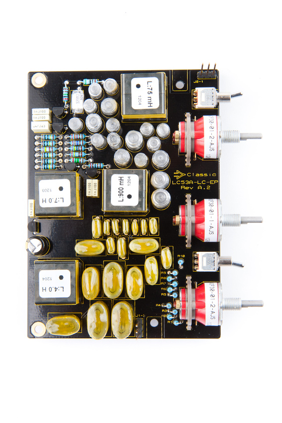
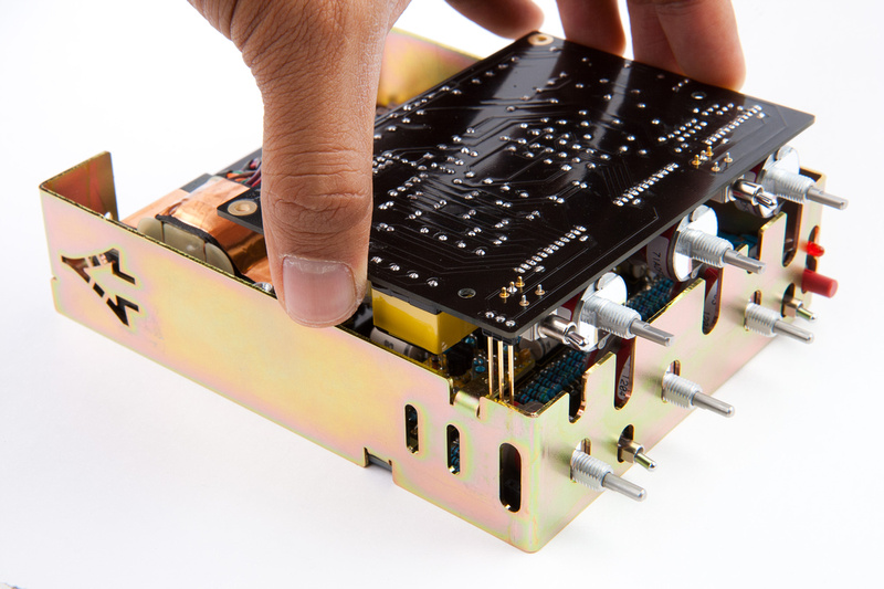
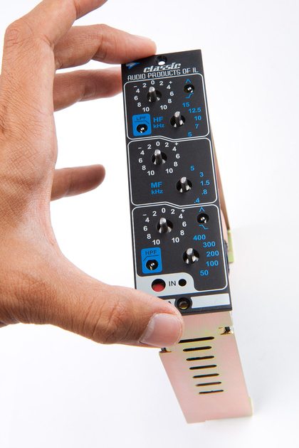
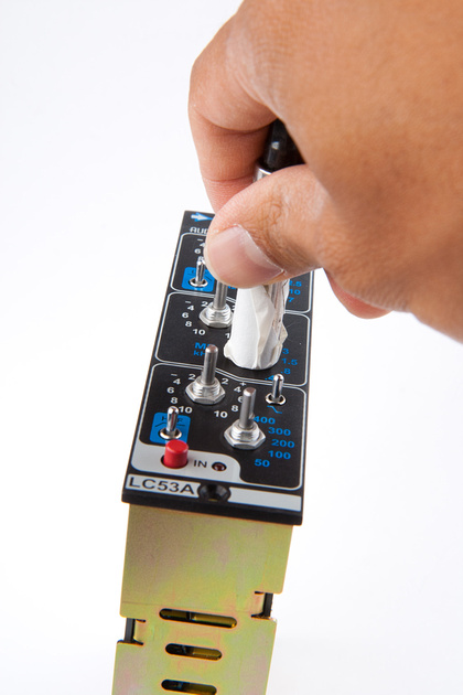
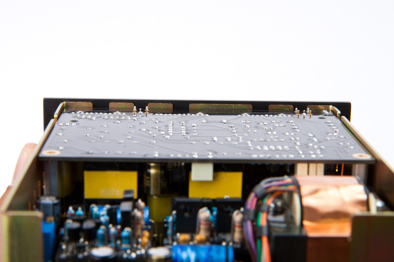
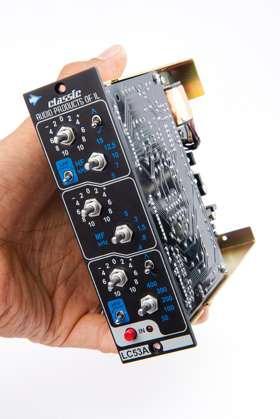
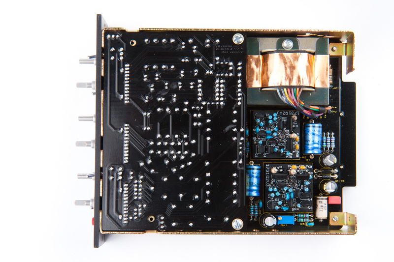
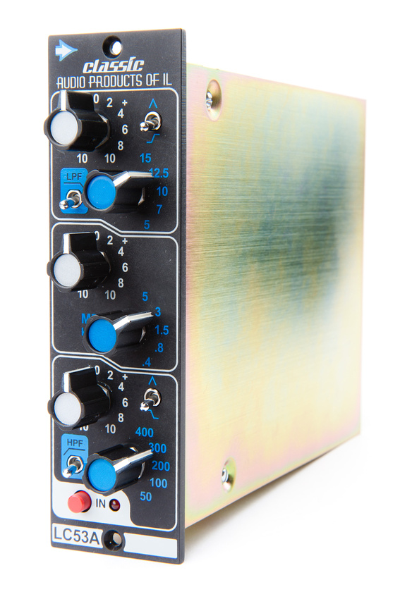
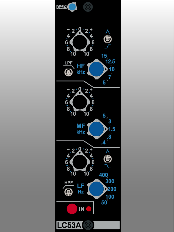
Rev B boards are now shipping for the LC53A. To easily identify, the Rev B boards are green and they have the CAPI® label affixed. The receiver circuit has been changed so that a CMRR adjustment is no longer needed. Besides that, most of the circuit is the same. To find out what else has been changed, please read the Rev B Addendum. Like with all projects, it is crucially imperative that you follow the BOM that matches the revision of the PCB that you are building.
--------------------------------------------------------------------------------------------------------
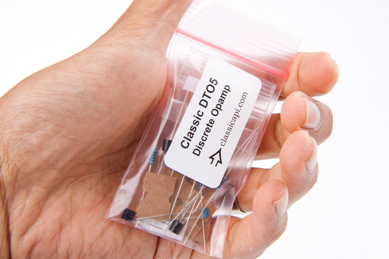
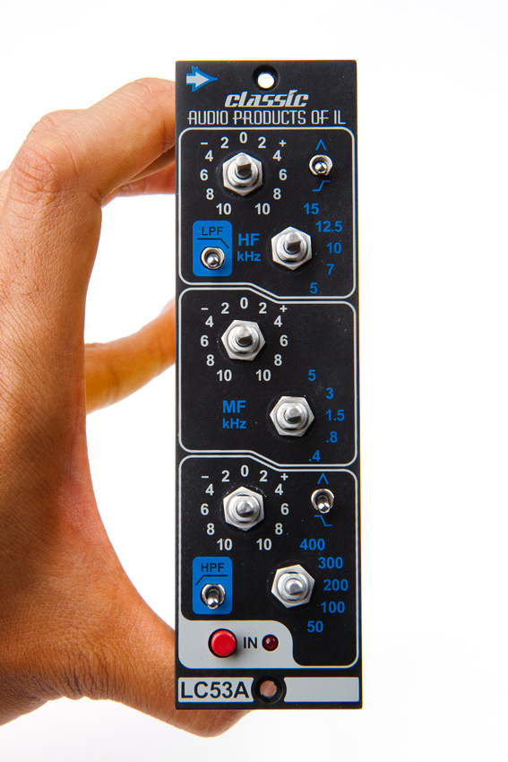
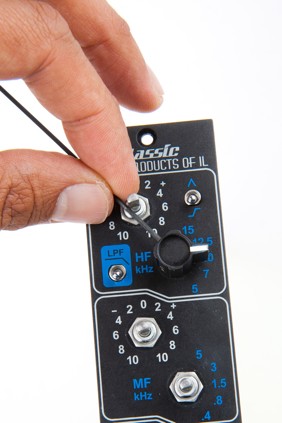
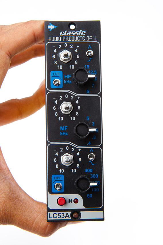
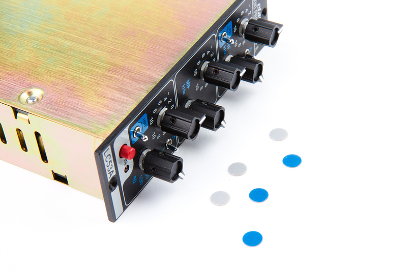
Some details can be found here http://capi-gear.com/catalog/product_info.php?cPath=22_117_119_171&products_id=327
Cheers, Jeff
**This is a semi complicated build. It is very important to read completely thru the Assembly Aid before starting on anything. There are some points made in the doc that can save you much time and prevent crucial errors during the build.
--------------------------------------------------------------------------------------------------------
September 21st, 2015 Update:
All support docs for this project can be found on the recently added Support Docs page at www.capi-gear.com
--------------------------------------------------------------------------------------------------------
--------------------------------------------------------------------------------------------------------
March 5th, 2016 Update:
Rev B boards are now shipping for the LC53A. To easily identify, the Rev B boards are green and they have the CAPI® label affixed. The receiver circuit has been changed so that a CMRR adjustment is no longer needed. Besides that, most of the circuit is the same. To find out what else has been changed, please read the Rev B Addendum. Like with all projects, it is crucially imperative that you follow the BOM that matches the revision of the PCB that you are building.
--------------------------------------------------------------------------------------------------------
Some details can be found here http://capi-gear.com/catalog/product_info.php?cPath=22_117_119_171&products_id=327
Cheers, Jeff