M670 compressor

GroupDIY Audio Forum

Help Support GroupDIY Audio Forum:

This site may earn a commission from merchant affiliate links, including eBay, Amazon, and others.

Kingston

Well-known member
Joined
Nov 1, 2005
Messages
3,732
Location
Helsinki, Finland
Parts of this project may be familiar, since it's based on the infamously unreliable and unstable PM670. There has been oscillations, lots of distortion and as many dead power supplies as there have been builders. The foundation is decent, but it seems no one ever took the time to walk through the issues. Everyone just settled for a stomp box that weighs significantly more than a boat anchor. And not even a single person ever measured the specs! Sometimes the people on this forum baffle me. Not all "color" is good. And no, tubes are not supposed to distort any more than solid state! If they do, the design sucks or it is a guitar amp.

Scrap the non-working parts, remove areas of unreliability. Simplify where possible, use parts that are available everywhere. What's most important, everything is rigorously tested and measured.

M670 compressor.

M670-schematic-Kingston-web.png


Things to note.

None of the transformers need center taps. Lots of substitution choice.
No one likes making 21-step rotary switches and no one should when there are easier and more reliable choices.
Plate configuration may look similar to UA177/176, but it's not. The cap makes all the difference.
V1 and V2 tubes need to be matched, but it's not essential for decent performance.

M670-PSU-Kingston.png

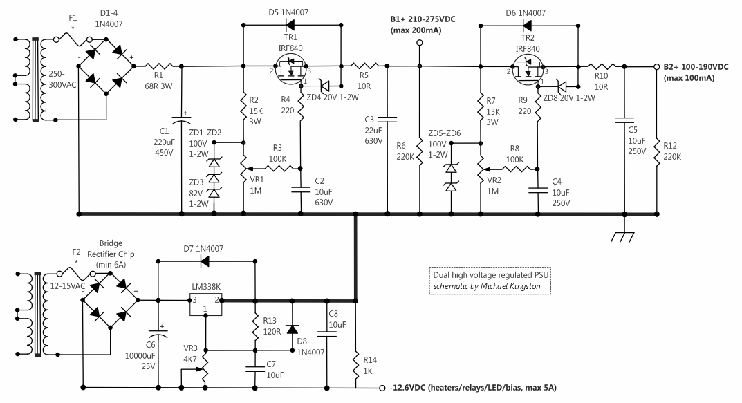
This PSU easily powers two channels and greatly simplifies wiring. Parts count is low and safety is good. Only two electrolytic caps in the whole project! Live long and prosper. Less explosions and very long term reliability. I know there's at least one other person in the whole world who appreciates these kinds of choices.

M670-spec-Kingston.png

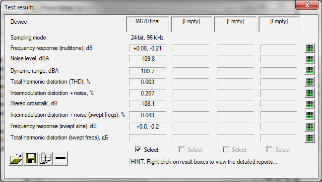
RME HDSP AD/DA input and output set to 0 dBFS (+13 dBu).

This can be expected from a successful build, lots of headroom and very low distortion. Frequency response is +-0.25dB at 10hz-40khz by the way, in case one needs to master dog or dolphin music. This measurement was with B+ at 150VDC. THD and IMD is about one quarter lower with 200VDC. Implementing a switch between these two is a good idea since compression performance and sound is different between the two.

The way I implemented this project was a combination of hand-knitted veroboards and hacksawed PM660 PCB's. I don't recommend this. This limited some choices, like bigger alterations of sidechain which can be optimised with use of ECC99/6N6P tubes. Scamp sidechain booster works great with this. I will post a tube matching rig with an easy to use excel curve matcher later.

I'm in the early stages of learning Kicad because I want to use at least this PSU as a generic lab PSU. There might be some PCB's in the future.
 
Kingston said:
...
V1 and V2 tubes need to be matched, but it's not essential for decent performance.

Decent performance : I can't agree with you on that point... Un-matched tube in a "vari-mu" use means thump and distortion... But here again, different poeple, differents feelings.
All the rest is nice and clear.

PS: I would modify the tube SC amp to an opamp one as it's a lot more easy and cheaper with opamps... But it's another point.
 
Thanks Kingston - some really interesting work there. You've obviously spent a lot of time improving a whole slew of things. I can really appreciate some of the changes would make a real benefit.

I for one am going to be pondering your refinements for a while yet.

Looks like some very clean performance figures.

Regards
 
4.7uf caps? 

Are you sure you want them? 

Have you measured the frequency response and other measurements of the circuit with the 4.7ufs?

 
Moby said:
Please don't make a same mistake as first "designer" of PM670. Tubes need to be close matched. Or just upload the sound sample of unmatched tubes 670 so people who like nasty stomp box compressors can decide ;)

First of all, this isn't PM670. Its problems did not leak here, I made sure of that. The plate output configuration with the cap makes a tremendous difference to cross-over distortion and thump. Try it and see. I'm somewhat surprised its not common elsewhere.

And when I said 'decent' I meant it. The spec I posted is with matched tubes by the way and not merely 'decent'. It's mastering grade. Best not get tangled into semantics.
 
Nice work Kingston!

But I also have not found a reason for the 4,7u cap as my PM670 does not have that offset DC problem.
 
So you all think I'm talking just to keep warm? Fine, let's assault with data then.

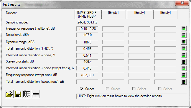
Here again, the matched 6N5P measurement from the original post:
M670-spec-Kingston.png


And here four tubes picked from a box at random, 6BC8/6BZ8 from various brands:
M670-spec-unmatched-Kingston.png


There is no thump, and as can be seen, THD% and IMD (mostly from cross-over distortion) is within very manageable and quite invisible range. This isn't some weak 0dBU "vintage level" measurement either, but blasted at 13dBu. Both tube sets sound equal when compressing, no farts, no burbs, no sudden thumping peaks.


.
.
.
.
.


Tough crowd, huh? Still not happy?

Here's the actual tube matching data of all tubes from the above tests:
http://www.michaelkingston.fi/files/6N5P-6BC8-match-chart-selection-2013.ods

The file is for the free Open Office. Column C "position in M670" shows which tube was used. Tubes 1-4 were cherry picked and represent a perfect match. Tubes test1-test4 are random 6CB8/6BZ8 from the box. Use the arrows "selected tube" to visually inspect compression performance.

Feel free to try this same thing with the poormans, see if they keep up.  ;D
 
Majestic12 said:
Should I design a pcb for this build ?
If a pcb is designed for this build, I'd add a pot in the cathode path like in the real 670... It will help builders to get an easier match between tubes...
 
lolo-m said:
If a pcb is designed for this build, I'd add a pot in the cathode path like in the real 670... It will help builders to get an easier match between tubes...

We don't need those ancient hacks anymore. You see, analag partially solved this whole tube matching issue with the negative cathode bias that moves the grid curves to a more linear range. Thus removing thump. What I did was significant reduction of cross-over distortion with this rearranged plate configuration. Best of both worlds.

Besides, builders are happy with 1-3% IMD with plain poorman apparently (best case tube matching scenario). Now you can have 0.5% (unmatched worst case), or far better.
 
Kingston said:
Gus said:
Have you measured the frequency response and other measurements of the circuit with the 4.7ufs?

facepalm.jpg

What does the above mean?

I asked a very good question.  You should ask yourself why I posted?  There are two basic reasons I questioned the use of cap coupling.  The posted measurements do not show a frequency sweep into different loads.  You added a cap to the transformer triode plate resistance interactive mess with other parts connected to them ONE more part to interact with whatever is connected to it.  You changed the loading on the triodes.  Sometimes when you "fix" one thing you change something else.


Strange that for something like 10 years nobody cared about measuring up and x-raying any compressor whatsoever on this forum. All of the sudden there is a feeding frenzy.

Perhaps that's a positive sign, but what I don't understand is the disbelief at the data presented. "It's all about the sound", they say. "I want more color". Why is it a surprise you have been listening to lots and lots of distortion?

Gus said:
I asked a very good question.  You should ask yourself why I posted?  There are two basic reasons I questioned the use of cap coupling.  The posted measurements do not show a frequency sweep into different loads.  You added a cap to the transformer triode plate resistance interactive mess with other parts connected to them ONE more part to interact with whatever is connected to it.  You changed the loading on the triodes.  Sometimes when you "fix" one thing you change something else.

I'll provide you with the requested sweeps sometime soon. 600ohm? The previously mentioned 10hz-40khz -+0.25dB was into 10k.
 
Especially when I specifically mentioned I'm learning Kicad for these exact purposes.

A mid-powered solid state sidechain will come into question sometime soon as well.
 
[silent:arts] said:
I think you should not be so rude to analag and his original design.
Some comments are unnecessary, unfair and wrong!

The original "design" is some spice concept that had not been tested in real world prior to your PCB work. Analag didn't help fix any of errors, shared none of the design data, and everybody was left guessing, including you!

Still you were perfectly fine selling that incomplete and broken product for years. :mad: It pisses me off people like you shroud under some blanket of doing a "service to the community" when obviously you are here to make money. The majority of this forum being paint-by-numbers crowd don't care or understand, but I do and I'm perfectly within my rights to be aggravated.

All this critique should have happened years a go. This forum has become stale and non-productive because of problems like this. Look at reply number 12 as a prime example. He didn't even bat an eye, and neither did the people how "liked" the post.
 
I strongly recommend everybody to calm down. There is no reason to discuss this topic in such a harsh tone. As far as I remember there was a quite long discussion before the pcbs were released. Analag had a prototype. I think you all remember his monster compressor with self wound transformers. Here is the thread:

http://www.groupdiy.com/index.php?topic=26887.0

regards
Bernd
 

Latest posts

Back
Top