how to caculate gain of non-invert opamp ?

GroupDIY Audio Forum

Help Support GroupDIY Audio Forum:

This site may earn a commission from merchant affiliate links, including eBay, Amazon, and others.

login721

Active member
Joined
Jan 14, 2012
Messages
30
Location
Vietnam
Hello , i have a question about caculate gain of opamp .
In the image below , gain of the OA1 is G=1+R1/R2 .But how to cacutate gain of the OA2 and OA3 ??
Thanks in advance!
sorry for my bad English!

opampgain-1_zps41ef84c3.png
 
usekgb said:
The gain of an inverting op-amp is R(feedback)/R(input).

thanks you .In my case is non-invert opamp .the input will go to In+ pin of opamp .But i don't know how the diode will effect the gain ??
 
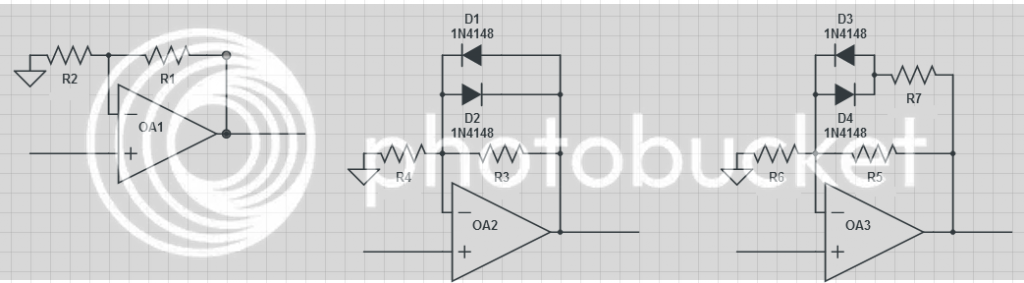
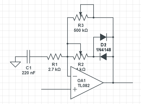
For very small output voltages, the diodes are off. So gain is determined by R5 and R6 only. For high (positive or negative) output voltages, the diodes are forward biased. As a first approximation, they can be viewed as short-circuit in this case, so gain is determined by (R5 in parallel with R7) and R6.

The exact behaviour of such a circuit is complex, and most easily analyzed using a circuit simulator. Also google "picewise linear amplifier".

Samuel
 
Yes also called "diode break" amplifiers, and these can be used to create non-linear transfer functions, Some early sine wave generators use variants on this to turn a triangle wave into a curved sine wave.

There is not a simple one number answer for AC gain, but one for low voltage gain when diodes are not conduction, and because diodes only conduct in one direction, positive and negative waveforms can exhibit different behavior.

JR
 
Thanks you guys!
I want to make an electric guitar overdrive stom box.R3 to adjust gain , R2 to adjust how early the signal will be clipped . Is there any problem with my schematic ? can you give me some advice please !
Thanks !

spds_zps21ed6af1.png
 
Guitar effects are subjective so hard to give simple definitive advice. You may want to also play games with shifting how different frequencies get clipped.  You need to listen to the results and experiment.

JR

 
I used the OA3 circuit in my 1973 dissertation for my degree in electronic engineering. It is more commonly known as a piece wise linear approximation circuit. You can add further diodes and resistors so that the desired function is approximated by a series of straight lines. The title of my dissertation was An Improved Compressor/Limiter.

Cheers

Ian
 
Just a note on your Overdrive.  The diodes clips at the .7volt or .3 for germanium and in each direction of the wave.  so gain just drives the non inverting into a clipped sound but usually with a triangle looking wave for output.

A note though is in a non inverting you have an output of 1 + rf /r in .  Complex as some have suggested but you will have a clipped input summed with a non clipped signal which is the +1 signal.  I have never liked the sound of this kind of over drive because there is a phase difference between the +1 non inverting and the feedback of the inverting distorted signal.  It creates an almost congested sound on the guitar but thats my opinion only.  Lots of other people like this.  I find a buffer transistor in front of the neg input feeding the guitar into the clipping side only, sounds better than using the + input(undistorted) +1.  You still have a high input impedance for the guitar with the buffer in.  There is info on the internet about this somewhere.

A good thing about your circuit is that as you play softer and harder, you force a dynamic clipping characteristic with your touch.  Most players like dynamic touch. A real guitar amp is a series process of distortion and touch.  (Not a clean signal plus a summed distortion. )  As I said i'm not a big fan of non inverted input with clipping on the inverting input.
 

Latest posts

Back
Top