efinque
Well-known member
- Joined
- Jan 3, 2018
- Messages
- 381
Sup GDIY,
I know similar discussions exist but I couldn't find anything that made sense to me.
Anyway, having built several DIY kits with opamps I decided to bite the bullet and try to design my own preamp. I've been breadboarding for a couple of days, then I ran into a problem while designing and prototyping a discrete preamp.
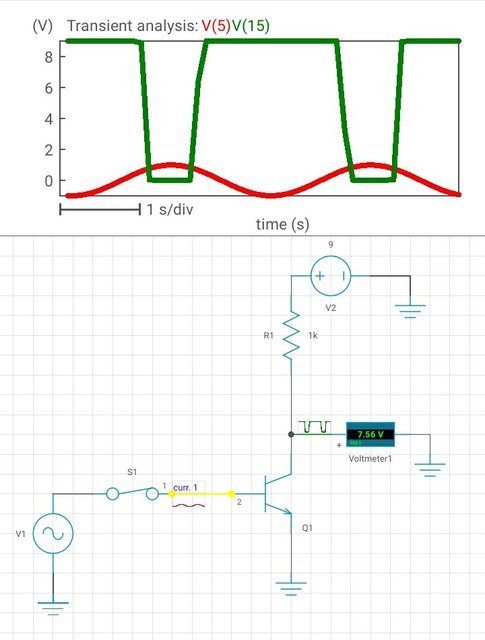
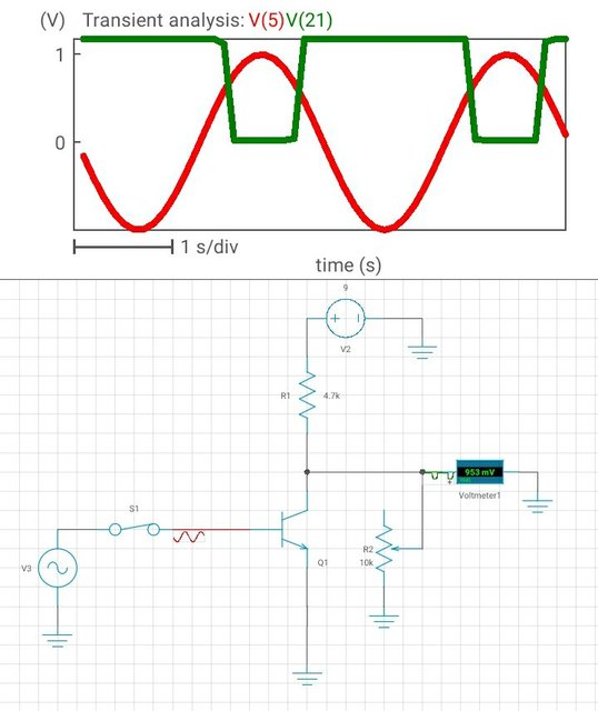
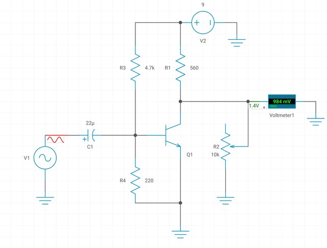
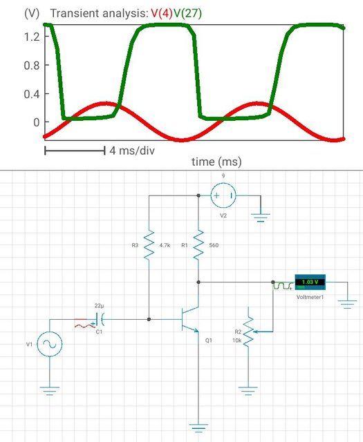
Here's the schematic :
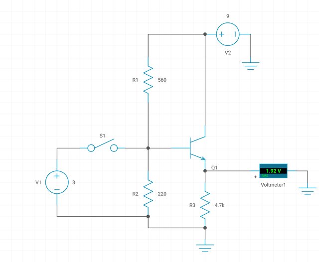
The tutorial from which I copied it from used a coupling capacitor in the input, is there a "standard" value for this?
I used a 3V CR battery (V1) to switch the transistor. V2 is a 9V battery.
Now, the problem is I get 2,02V output in my DMM when V1 isn't connected and 2,03V when it is so in theory it's working but I'm not sure it's safe to plug any sound sources or headphones into it.
I reckon I should change the resistors values but I don't know where to start, are there any rules of thumb to this?
EDA simulations showed me a PNP transistor is easier to design with, is this true? I only had one, a BC547 which is NPN, should I go straight for an opamp such as NE5532?
I also read about biasing.. If I understood correctly it takes place in the node between R1-R2 but I didn't quite grasp the concept.
Thanks in advance,
-ef
I know similar discussions exist but I couldn't find anything that made sense to me.
Anyway, having built several DIY kits with opamps I decided to bite the bullet and try to design my own preamp. I've been breadboarding for a couple of days, then I ran into a problem while designing and prototyping a discrete preamp.
Here's the schematic :

The tutorial from which I copied it from used a coupling capacitor in the input, is there a "standard" value for this?
I used a 3V CR battery (V1) to switch the transistor. V2 is a 9V battery.
Now, the problem is I get 2,02V output in my DMM when V1 isn't connected and 2,03V when it is so in theory it's working but I'm not sure it's safe to plug any sound sources or headphones into it.
I reckon I should change the resistors values but I don't know where to start, are there any rules of thumb to this?
EDA simulations showed me a PNP transistor is easier to design with, is this true? I only had one, a BC547 which is NPN, should I go straight for an opamp such as NE5532?
I also read about biasing.. If I understood correctly it takes place in the node between R1-R2 but I didn't quite grasp the concept.
Thanks in advance,
-ef


