THAT4301 compressor

GroupDIY Audio Forum

Help Support GroupDIY Audio Forum:

This site may earn a commission from merchant affiliate links, including eBay, Amazon, and others.
does any of you know why R16 is labeled 30k1, while its a 30k on the schematic?

here is a schemo/block drawing of what i have built (just added THAT i/o stages):
http://beatbybit.com/gears/Channel_4301_002.pdf

can you please check and see if im missing something?
the "InputGain" A10k pot is set to max. should i remove it?

some quick measurements (RME FireFace800) :

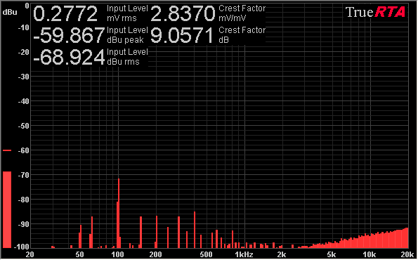
self noise of the THAT i/os + the 4301 v1.6:
4301_RTA_001_N.png


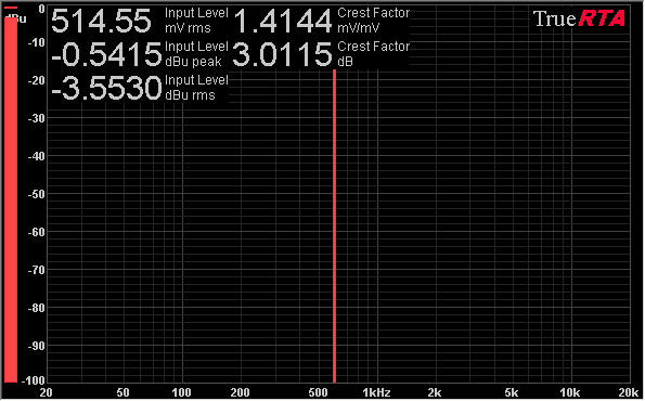
600Hz sine (-12.9dBFS on my RME, that should be 1.414V P-P?):
4301_RTA_001.png


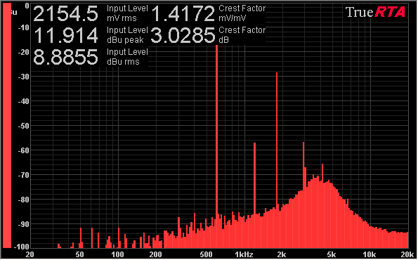
both at 80%-ish Threshold, inf Ratio, and max Gain

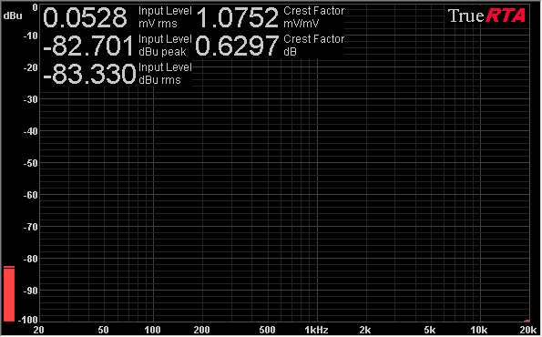
here is the THAT i/o alone (4301 out of circuit) / self noise:
THAT_i-o_RTA_001_N.png


600Hz sine:
THAT_i-o_RTA_001.png
 
How can use master RMS chain and break slave channel control signal chain?
What are the components don't use and place in the PCB for this configuration?
 
Tata,
Are you hearing any radio frequencies? I just put together a channel and I had the ratio pot off board and I could hear talk radio through the compressor. I Disconnected the wires and talk radio disappeared. 
 
thanks burdoto,

i will try it as soon as ill get a B5k potentiometer that fits the PCB.
got any ideas about the distortion, please?
 
I seem to have some distortion in rms mode as well, but with serious compression. I have only been running a tone and some drum tracks through it. I haven't set to solving that. Some one else mentioned the rms mode changed the behavior of the ratio and it seems that way for me as well. Like the ratio is much higher in rms.

On a side note. Anyone know why r19 was removed? Does r19 affect the scale of the ratio pot? I seem to be getting 4:1 ratio with a very small turn of the pot; Approximately 680 ohms.
 
When we build a stereo unit... What jumpers in the slave pcb v1.6 are used?
I don't see in the 1.1 schematics notes.
 
The radio frequency interference I was experiencing was silenced when I connected xlr pin 1 to ground. The wired ratio pot was not the culprit. My unit is quite quiet now. I'm also not using the 0v connection on the board in between input and output, only the 0v at power connections. 
 
Somebody can answer my questions?
I posted a few messages and nobody help me.

Thanks.
 
Jitter,

sadly i dont know the correct answer to your question, but iirc i saw some comments earlier in this thread about the stereo version.
also maybe this can give you some ideas : http://www.d-r.nl/assets/compressor-manual-serv.pdf  ? (stereo 4301, schematics at the bottom)
and maybe this too, tho there is no schemo available (but all the other docs):
http://l-1.su/Microcompressor_stereo.html

 
Excellent project!

Planning a 4 channel mono build for utility comp.

I've a few questions about adding some features I want.

1. Gain reduction meters

I've read the  thread and seems someone had success adding meters showing gr reduction. I've got some 1ma meters. As far as I can see I can take a feed from R19 or just after the ratio wiper, buffer it and that should work? Maybe use some trimmers in the buffer circuit to trim to correct response.

2. Output or input transformers

Would like to add some iron on the output (or input might be better) for a bit of colour.  I've seen a run of pico comps with cinemags.  OEP A262A2E maybe a good cost effective choice as they are cheap and I like the sound.  Any suggestions welcome and also what's the best input or out?

Case has been party made so I'm on my way ;-)


Attachments

  • image.jpeg
    image.jpeg
    1.5 MB · Views: 177
Ok, I've been doing some testing on the units. I've noticed in peak/hard mode there is some audible harmonic distortion. The distortion frequency is around double the test frequency of the signal generator.  And in peak/soft mode there is some audible distortion below the test frequency. This is with component values on the v1.6 schematic.

Interestingly, I have a stock Aphex 651 and it displays the same characteristics with additional higher harmonic frequencies, and the soft knee mode adds distortion as well. So the 4301 comp is not performing worse than the Aphex.

I read earlier in the thread that a higher value for C7 might help. I tried a 47n film capacitor instead it lowers both the higher harmonic distortion and the distortion below the test frequency. Should I try a value for C7 higher than 47n?

The RMS mode has also behaved strangely. With a 10uf tantalum for C9, my led meter shows solid GR(three db for example) with no variation and it doesn't seem like the signal is being compressed.  I have tried a 1uf  cap for C9 and the dynamic response definitely improves. I have also tried .1uf cap for C9 and the RMS mode behaves very similarly to peak mode.

Not sure how RMS mode is supposed to behave. Is lowering the value of C9 making Rms mode not RMS? Anyone have any advise about this?
 
I am looking for a clever way to link 2 mono units for stereo using 1 wire (like in a 500 series rack).  So far I can't figure out a way to do this,but there are a lot of smarter folks on the forum than me.  Ideas?
Thanks!
Best,
Bruno2000
 
Like with a single pole On/Off switch?

Only way I could think of is, link both the RMS filter caps (Pin 5 on the 4301) and still take the CV off the individual RMS outs (Pin 4) of the each mono unit, that will at least double the time constant and maybe cause some crazy interactions, but why not try? Just shooting the breeze, I´m not that smart anyway... ::)

Edit: like shown in Figure 1 here http://www.thatcorp.com/datashts/dn03.pdf
 
While building a 4301 compressor using the v1.6 layout, i stumbled accros resistor r12 (2M) which connects to V- in the schematic, but to ground on the pcb board.  Which one would be correct? The THAT notes 115  state V-, but connecting this way result in a malfunctioning treshold and ratio knob.
 
Sorry for long delay. V1.7 is available.
Errata: R12 (2M at the THAT4301 pin 2) goes to -15v (not to ground). You can solder it to R23 lead in v1.6 and previous.
Next (offboard wiring) - switch point SW2A (A2) goes after diode D2.
http://diy-tubes.com/image/data/manuals/THAT4301-v1.7-En.pdf
THAT4301-PCB-v1.7-0-500x500.jpg
 
Ooh  new PCB! Nice to see this project is still progressing.

Anyone made any progress with the attack/release mod?

Or had any joy making a stereo version?

Just finishing off a D-AOC and then I'll make a start on this :)
 
Basic question about compression ratio. I have v1.6 built (corrected switch connections) and I have not used optional 2M resistor R23. Any idea how to set compression ratios  (about) 1:2 to 1:4? Is the setting easier with 2M resistor? I only use RMS- and soft knee modes. My idea is now try to use this comp with vocals after a mic preamp. Simple gain reduction meter built.
 
Diydiy said:
Basic question about compression ratio. I have v1.6 built (corrected switch connections) and I have not used optional 2M resistor R23. Any idea how to set compression ratios  (about) 1:2 to 1:4? Is the setting easier with 2M resistor? I only use RMS- and soft knee modes. My idea is now try to use this comp with vocals after a mic preamp. Simple gain reduction meter built.
R23 has nothing to do with Ratio; it justs shifts the threshold control.
Without R27, 2:1 should be with the ratio pot half-way, and 4:1 at 3/4 rotation. With R27, the taper is modified so they come closer to CCW.
 

Latest posts

Back
Top