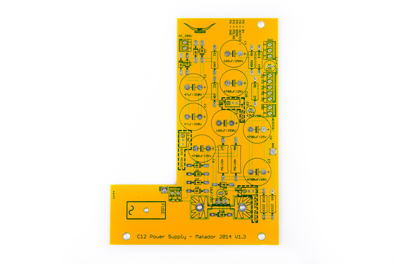
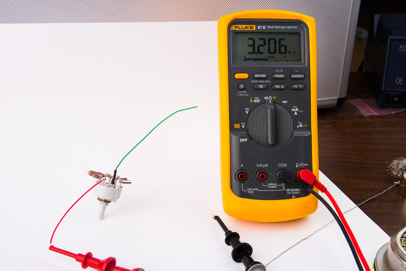
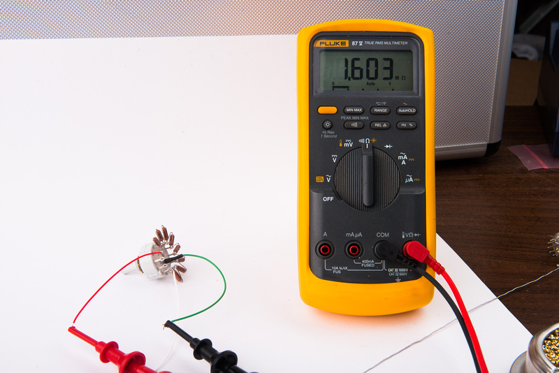
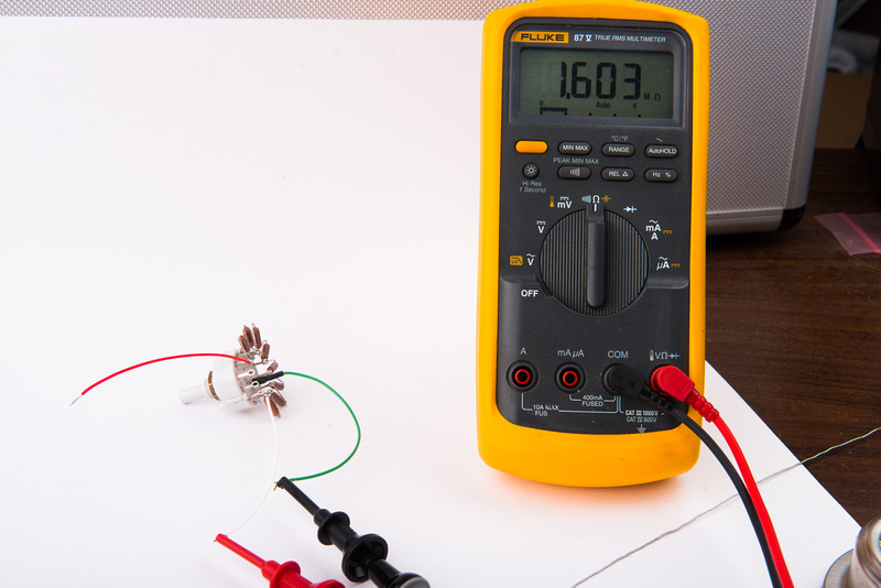
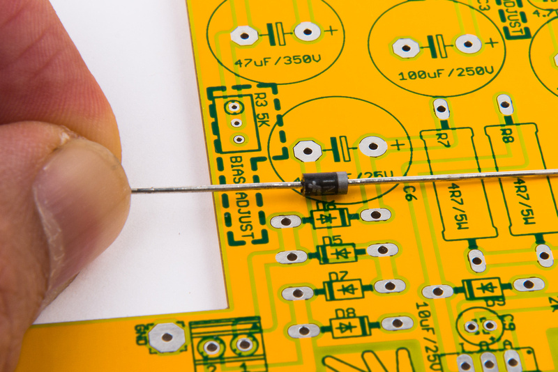
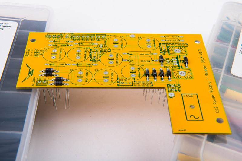
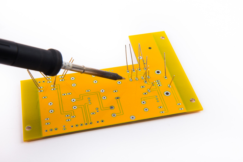
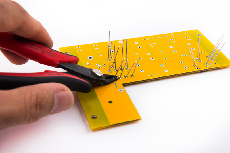
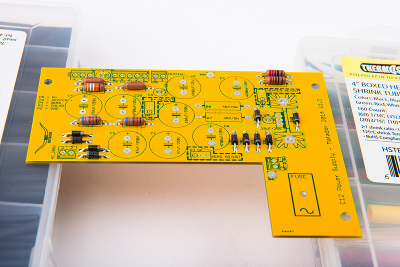
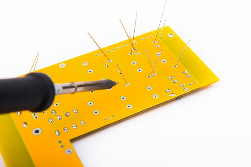
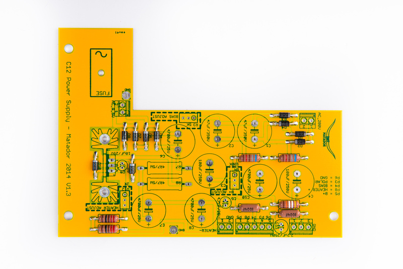
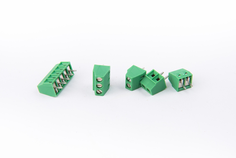
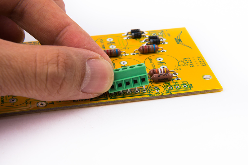
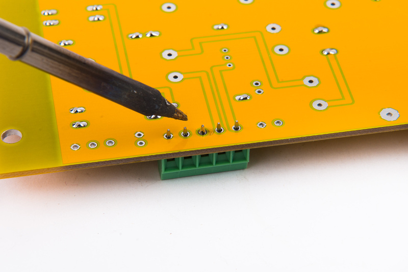
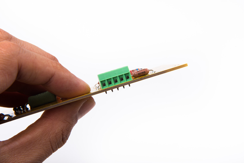
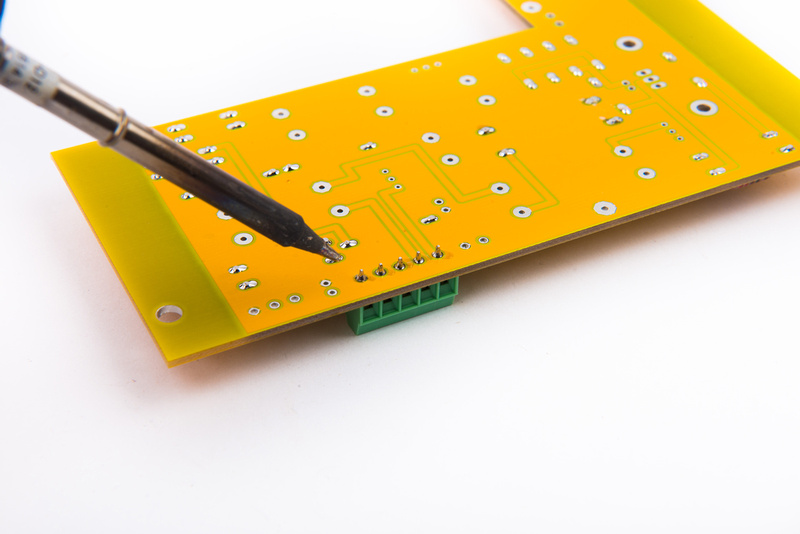
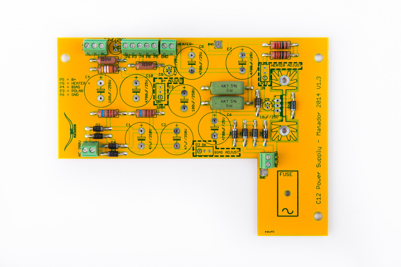
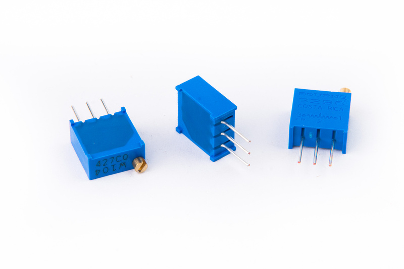
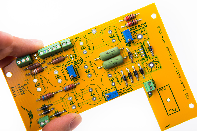
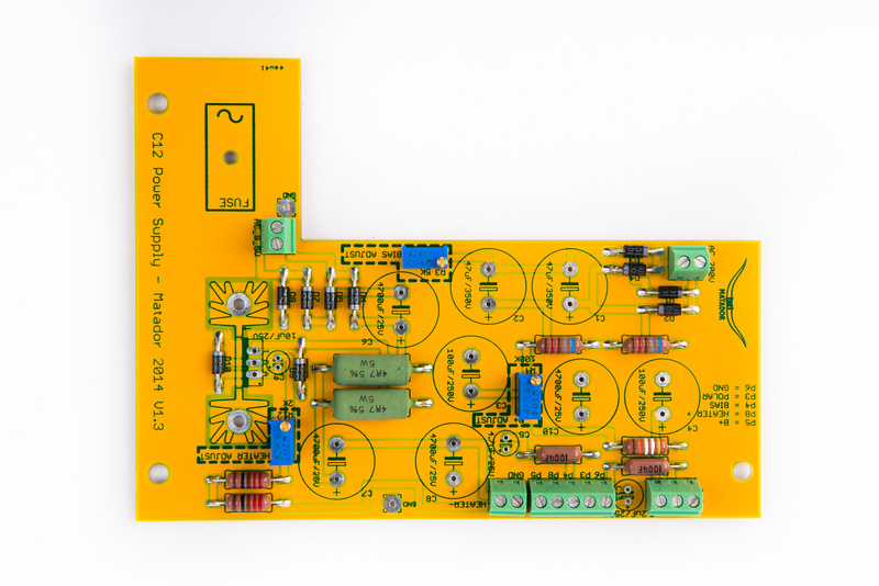
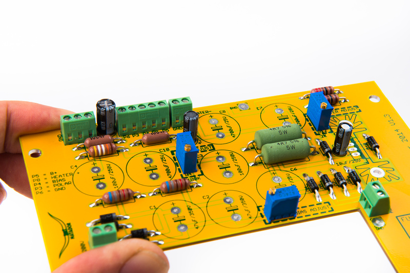
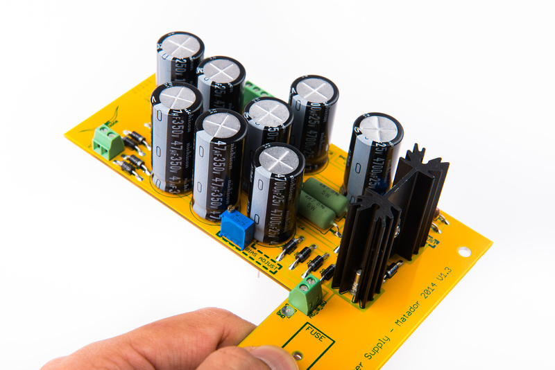
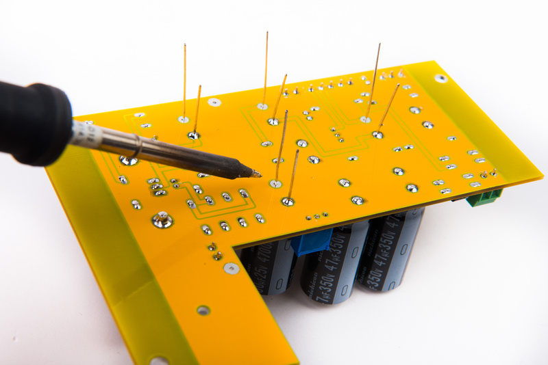
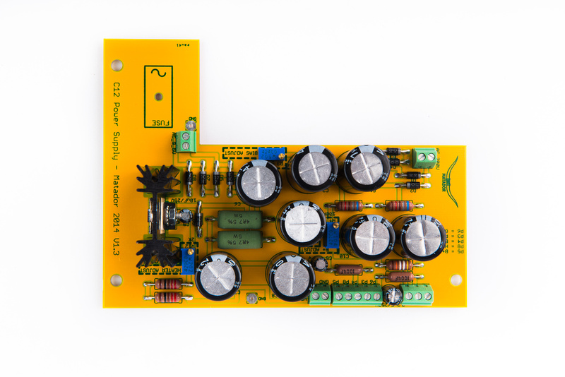
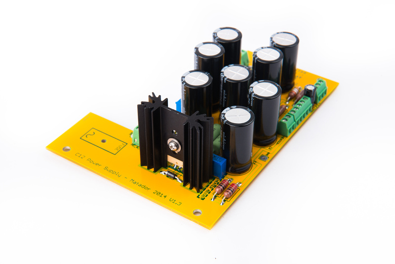
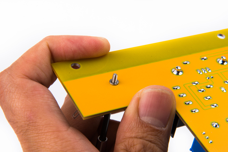
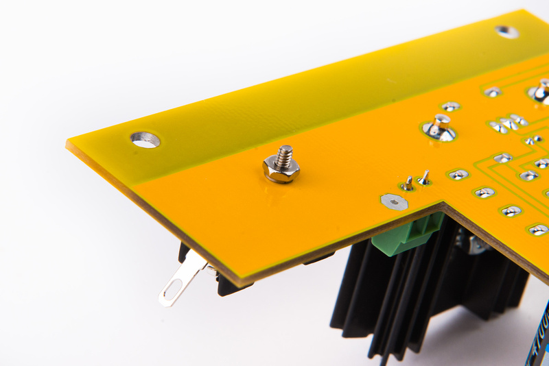
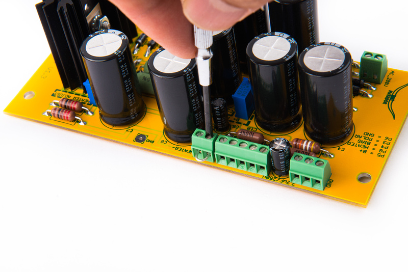
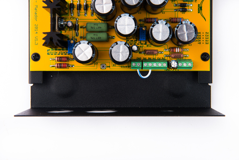
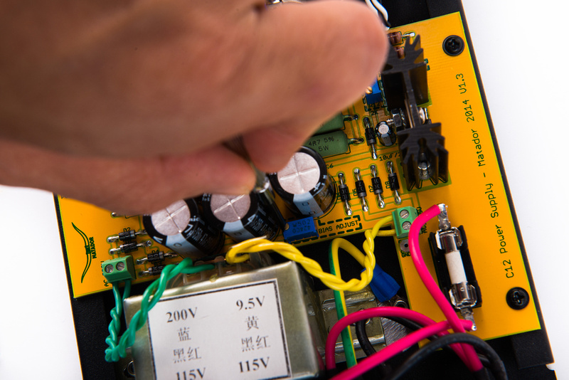
Next, locate the 3 trimmer pots.
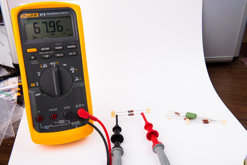
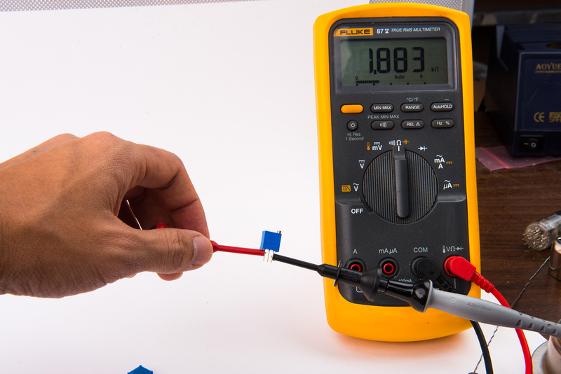
Note: It is a VERY common build mistake to assume these parts are the same value. They are not. Carefully confirm each trim pot's value by measuring resistance across the outside legs with a multimeter.
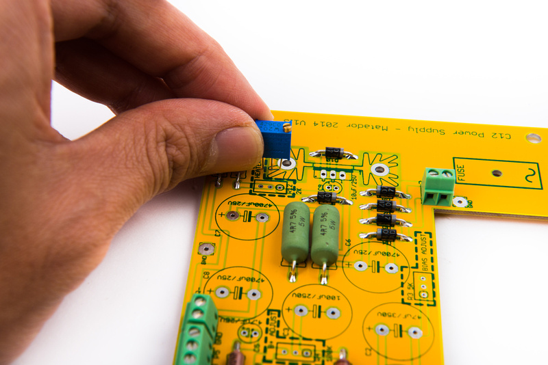
The position of the adjustment screw is indicated on the PCB silkscreen.
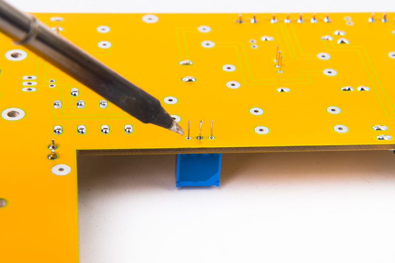
Position the trim pot and solder one leg only.
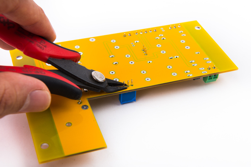
With only one leg soldered, confirm alignment and that the pot is seated flush against the PCB. Once aligned and adjusted, solder the remaining legs and trim the leads.
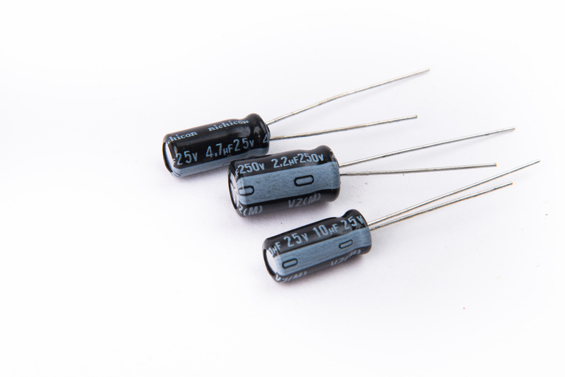
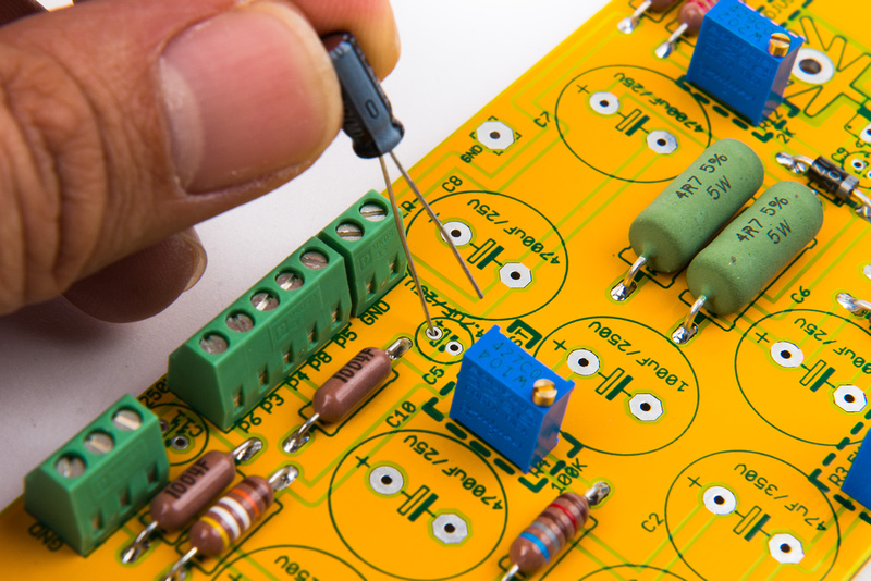
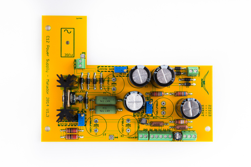
Next, locate the 3 small electrolytic capacitors.
NOTE: It is a VERY common build mistake to assume these capacitors are the same value. They are not! Carefully check the values indicated on each capacitor and make sure they are placed correctly.
C5 = 4.7uF 250V
C9 = 10uF 250V
C11 = 2.2uF 250V
Electrolytic capacitors have polarity and must be oriented correctly. The longer lead indicates the "+" side of the capacitor. Also, the side of the capacitor with the white stripe indicates the "-" side.
As a point of reference, all of the electrolytic capacitors in this kit orient the same direction.
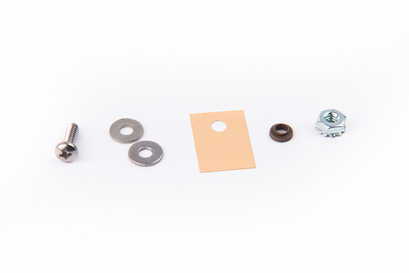
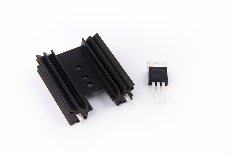
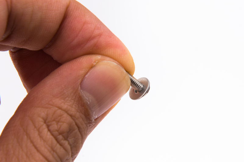
Next, we will mount the LM317 regulator for the heater. Locate the hardware to mount the regulator.
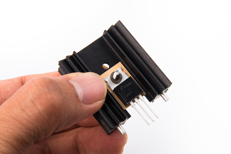
And, locate the heat sink and regulator.
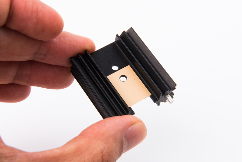
The insulator isolates the regulator from the heat sink. Place this first on the regulator.
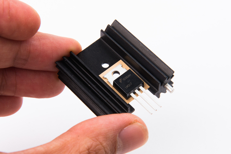
Next, place the regulator on top of the insulator.
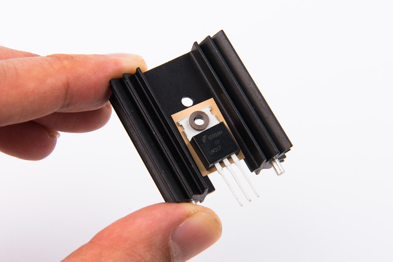
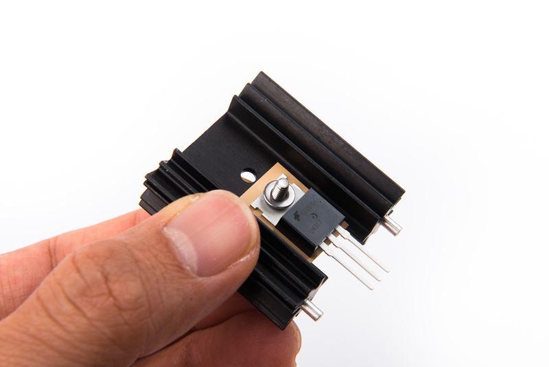
The plastic shoulder washer keeps the screw from contacting the regulator body.
Place a washer on the screw.
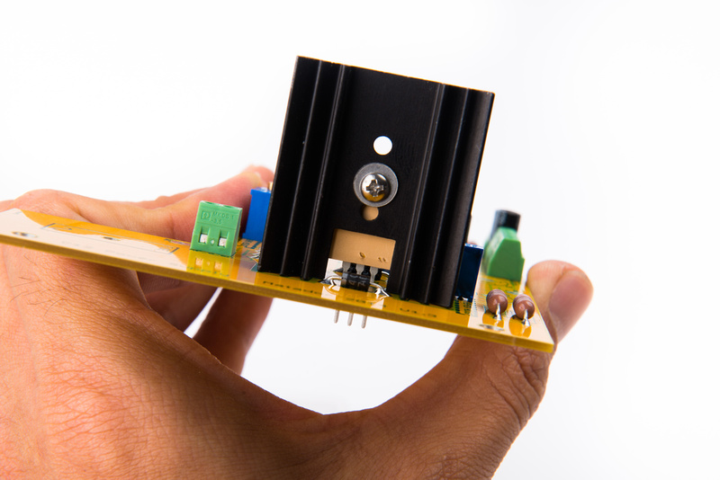
I choose to insert the screw from the back side so the screw slot will remain easily accessible for future repair.
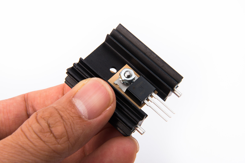
Another washer and the nut complete the regulator installation onto the heat sink.
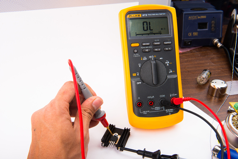
After tightening the screw, confirm that there is no continuity between the body of the regulator and the heat sink.
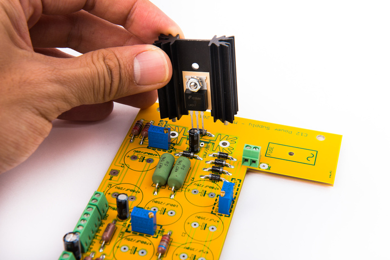
Next, place the assembly onto the PCB.
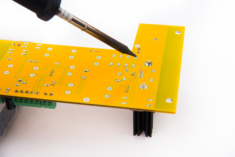
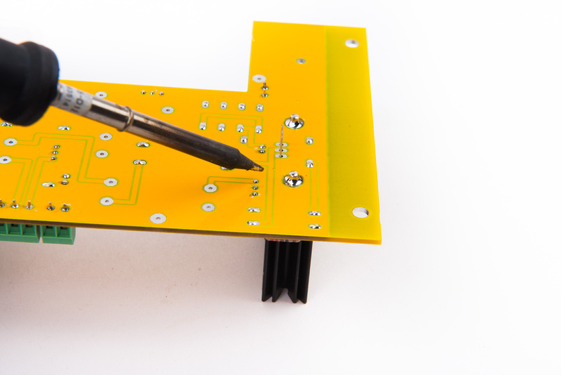
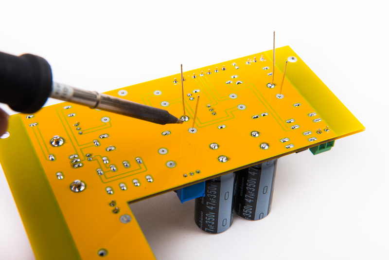
Increase the heat setting on the soldering iron to solder the heat sink to the PCB. Being as it is a heat sink, the component is quite efficient at dissipating heat from the soldering iron and can be difficult to solder. Attach one leg only.
Confirm that the heat sink is sitting firmly on the PCB surface. If the part needs to be seated tigher, press on the heat sink while re-heating the joint to re-seat it.
Once solidly positioned, solder the other leg.
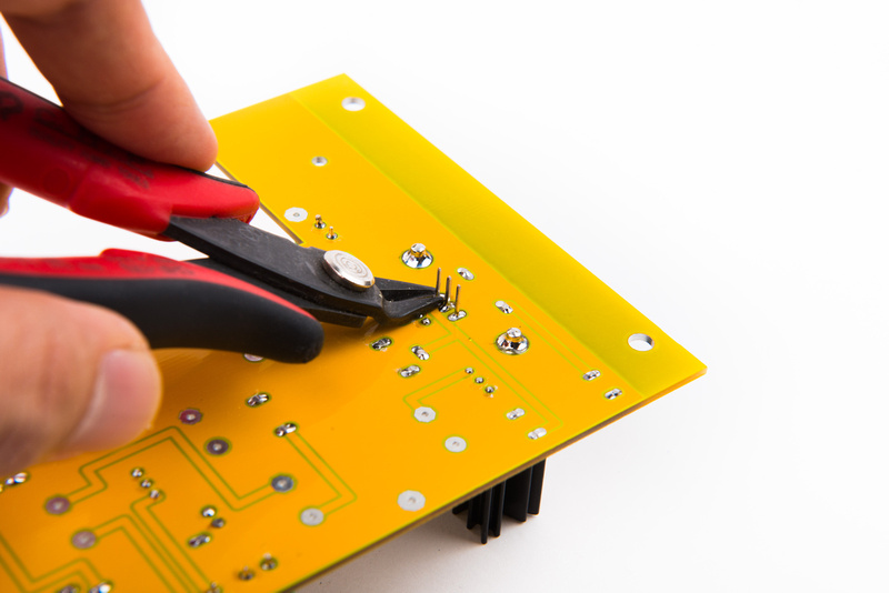
Reduce the heat on the soldering iron back to normal levels and solder the three legs of the regulator and trim the leads.
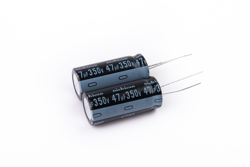
C1 and C2 are the tall 47uF 350V capacitors.
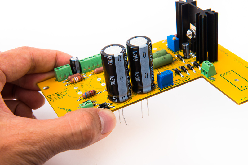
Once located, insert them into position. Be sure to heed the polarity of the capacitor. The "+" side is clearly indicated o the silk screen. Also, all of the electrolytic capacitors in this kit orient the same direction. I solder one leg first and then confirm that the capacitor is seated well to the PCB and standing straight. After confirming or adjusting the positioning, return and solder the remaining leg.
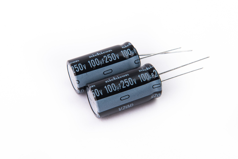
C3 and C4 are 100uF 250V
Locate and install in the same manner.
The B+ supply capacitors are now installed. Triple check that all of these are in the correct positions.
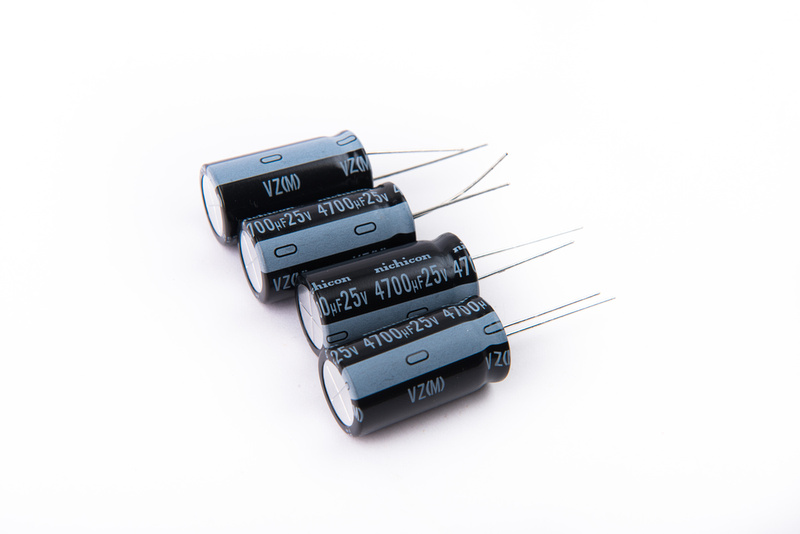
C6, C7, C8, C10 are 4700uF 25V.
Check again carefully before installing these capacitors to make sure they are correctly positioned. Then, solder them in place.
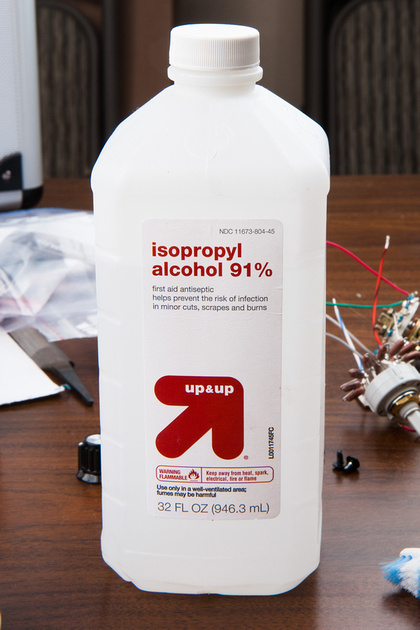
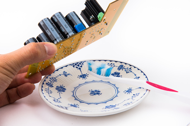
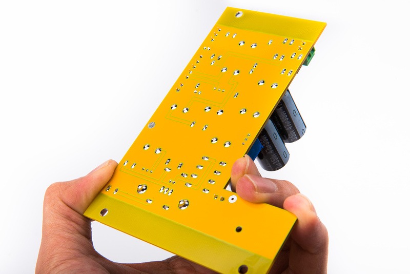
Next, clean the bottom of the PCB with isopropyl alcohol. There are a lot of new joints, so it may take a few passes to get the flux residue off.
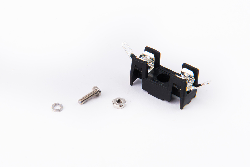
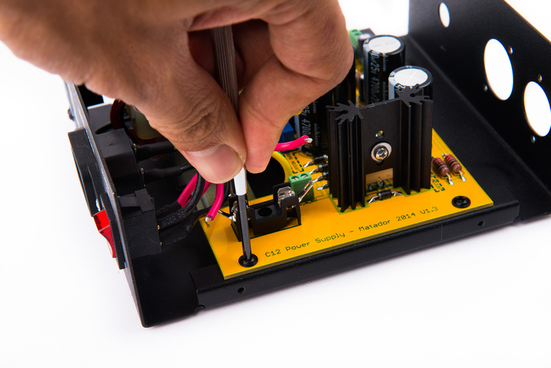
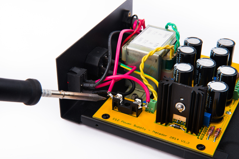
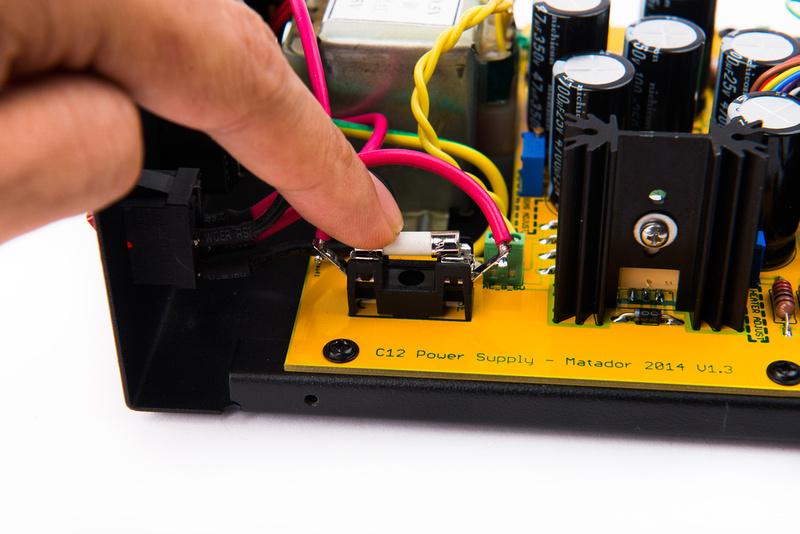
Locate the fuse holder and mounting hardware (2-56 screw, lock washer, and nut).
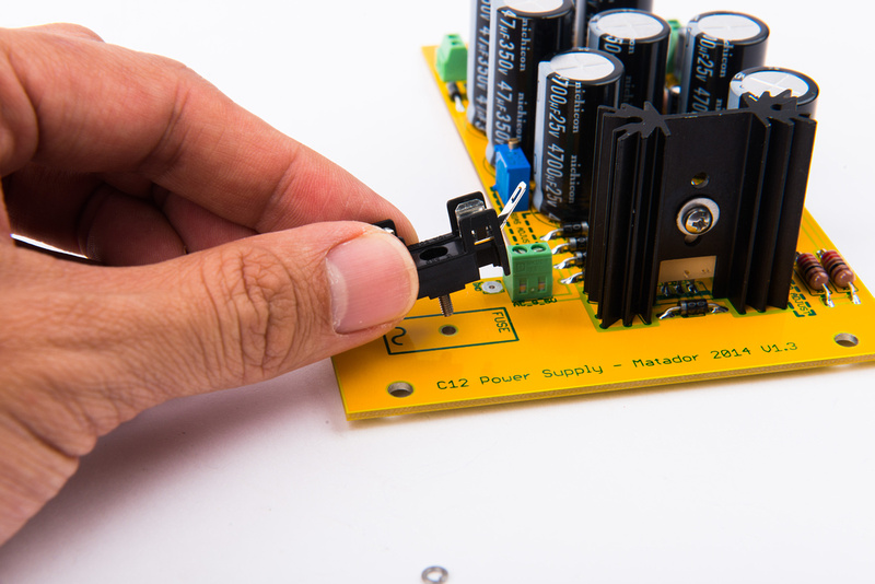
Place the screw inside the fuse holder and place the component.
Then, flip the board over and install the lock washer and nut.
For the AKG C12 or other microphone that requires a positive heater supply voltage, make a wire jumper from a capacitor cut-off lead.
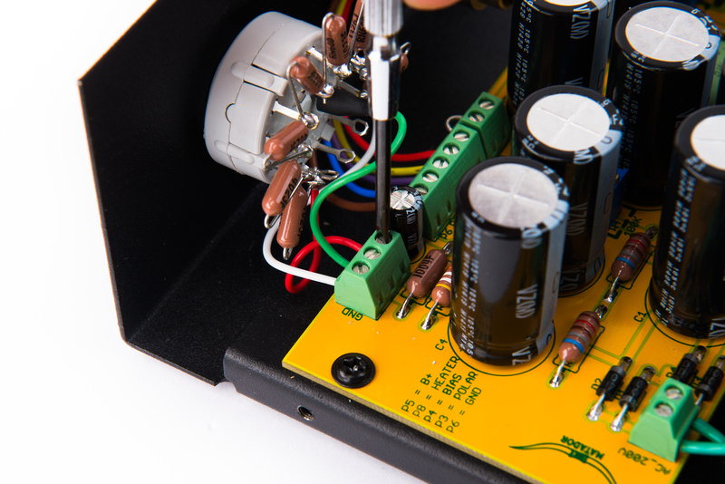
And connect "GND" and "HEATER -" at the screw terminal. In this configuration, screw terminal P8 outputs a positive heater supply voltage (ie. C12, ELA M251, etc.)
Alternately, if the microphone requires a negative heater output (ie. U67), simply jumper the "P8" terminal to "GND" with a wire and use the "HEATER -" terminal to supply your negative heater voltage.
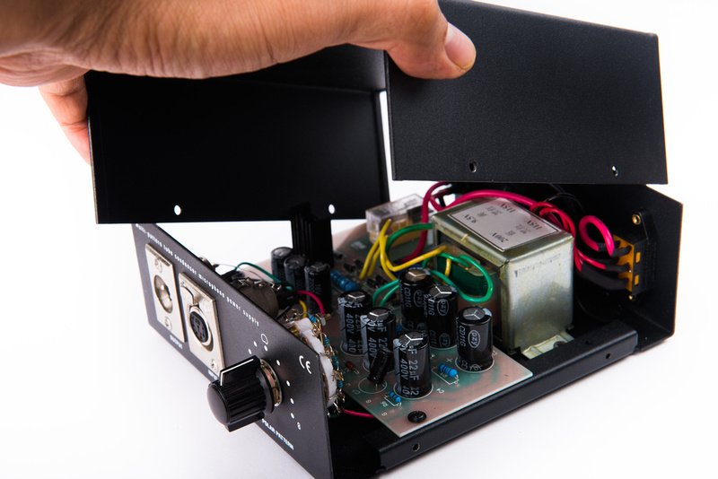
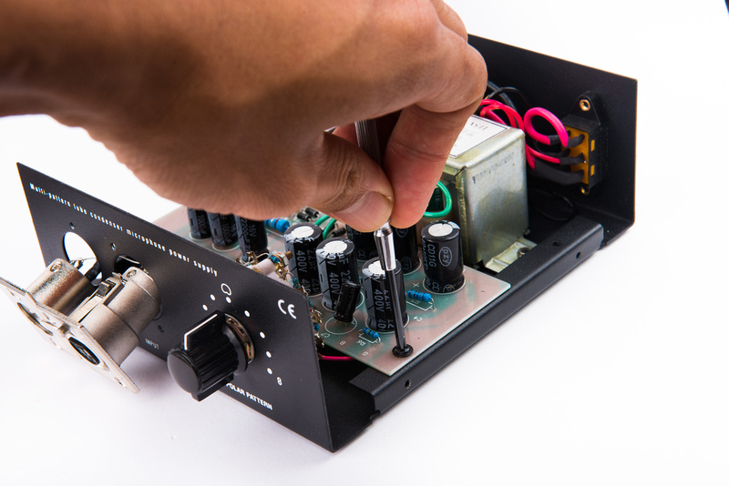
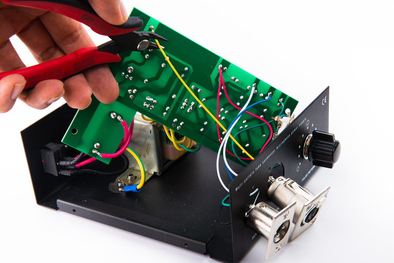
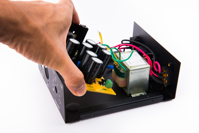
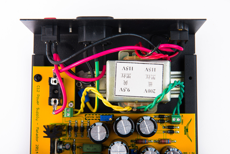
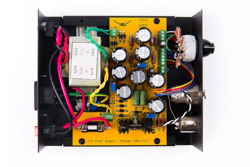
With the correct heater supply configuration selected, place the PCB into the chassis.
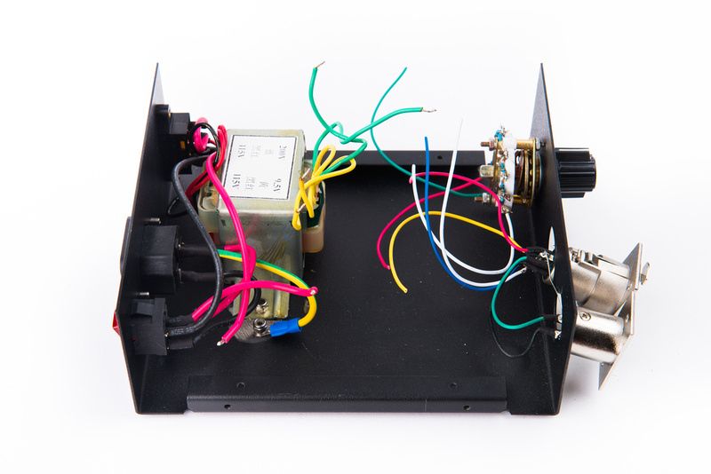
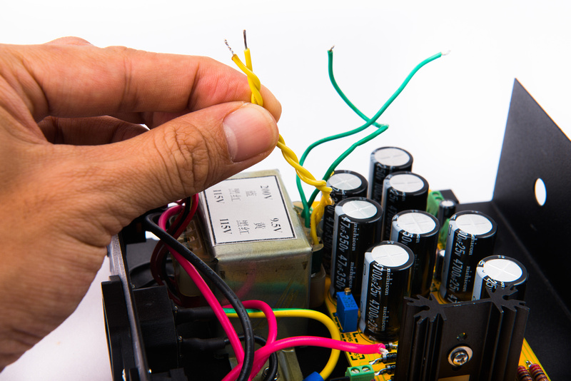
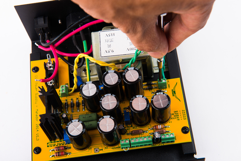
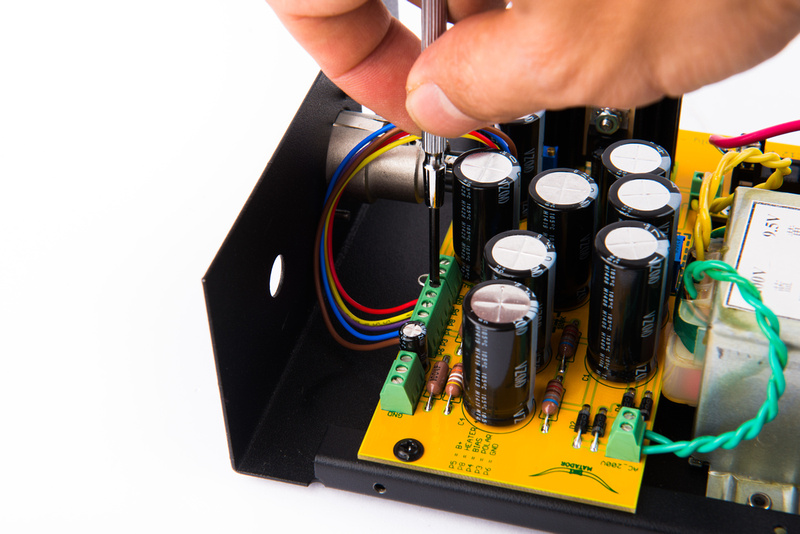
The yellow 9.5V transformer secondaries supply the heater side of the power supply. These wires should be twisted before installing into the designated terminal block.
And, the green 200V secondaries supply the B+ side of the power supply.
Re-connect the mains connections to the new fuse housing.
The A/C mains side of the power supply is now completed.
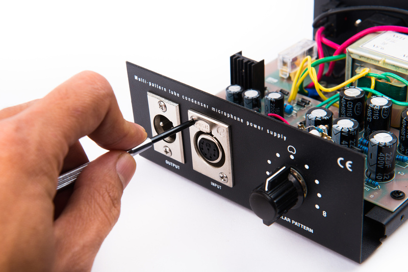
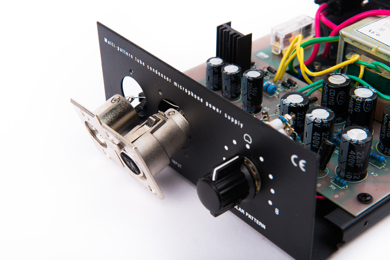
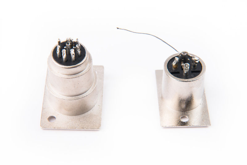
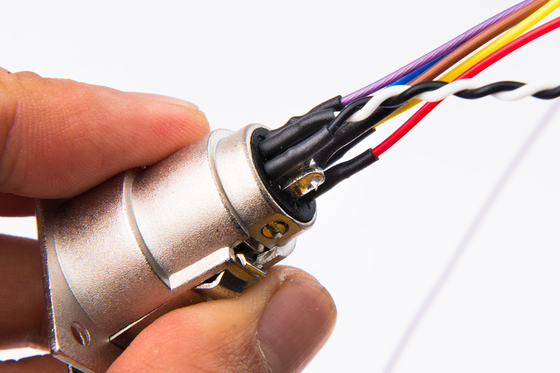
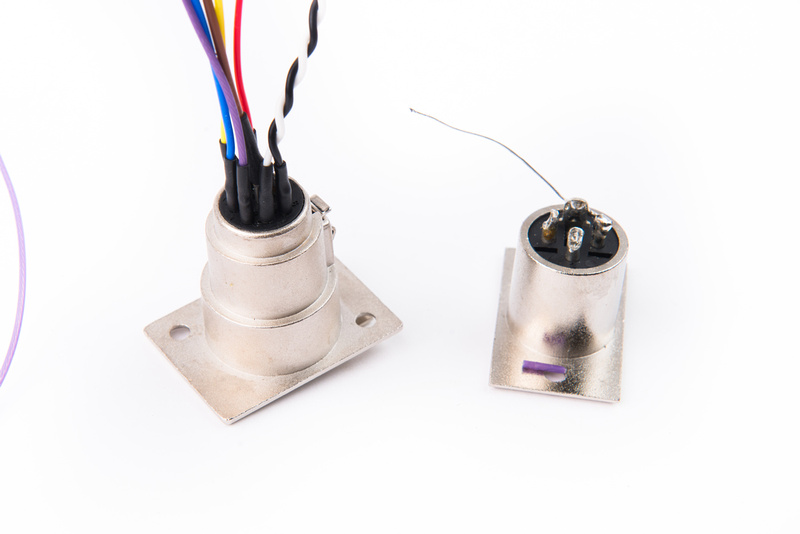
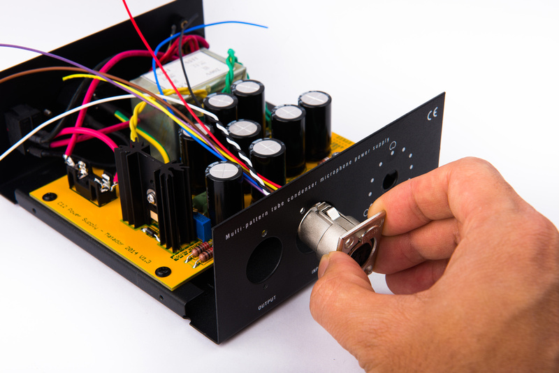
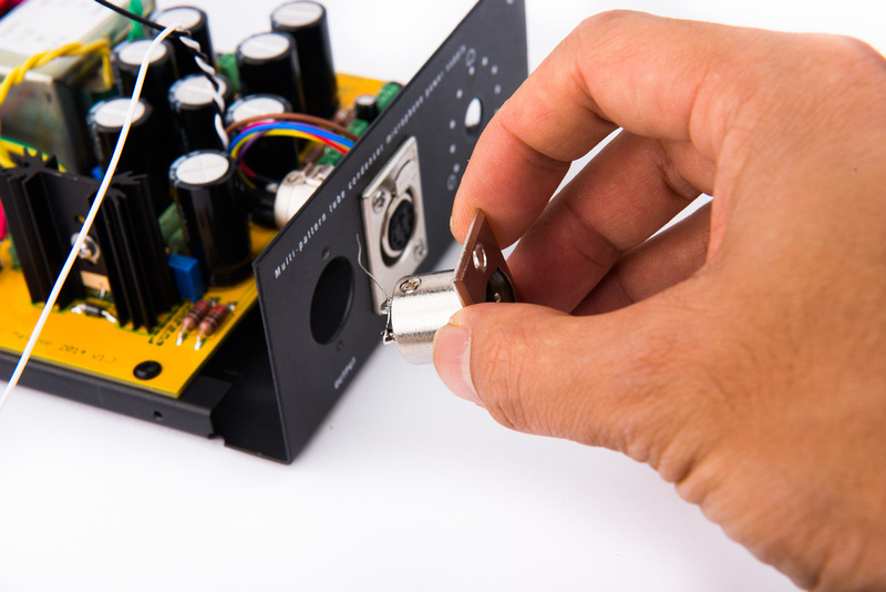
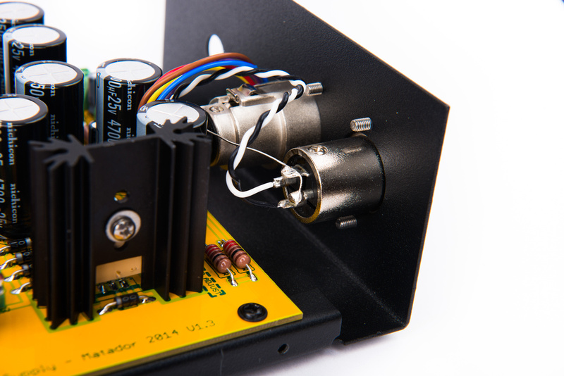
Next, install the 7 pin XLR connector that we prepared with fresh wires previously.
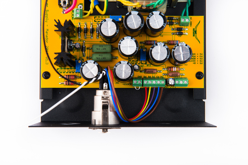
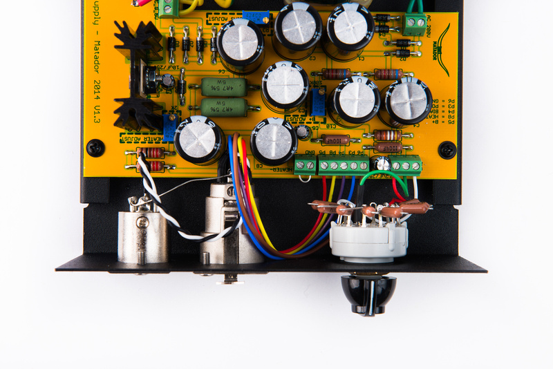
And route the wires to the designated screw terminals. The pinout configuration can be whatever you determine for your microphone build. It is critically important that these are consistent between the microphone and the power supply. Confusion here can lead to all manner of problems.
For this specific build, these are the pin designations that I selected:
pin1 = B+
pin 2 = heater
pin 3 = pattern
pin 4 = bias
pin 5= audio +
pin 6 = audio -
pin 7 = ground
For the most part, I have settled on this pinout configuration for all new tube microphone builds in the studio for consistency which allows me to place the 2 large gauge wires of the Gotham GAC7 cable that I use on pin 2 (heater) and pin 1 (Ground). The only deviation is on U47 type builds that combine heater and B+ together, I utilize pin 2 for the B+ in those builds so my expensive cables remain interchangeable between all tube microphones.
Here, you can see the 7 pin XLR wired to the PCB in positive heater supply configuration as the target microphone for this build is an AKG C12 clone.
Next, install the 3 pin XLR.
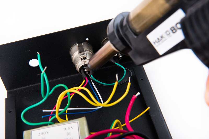
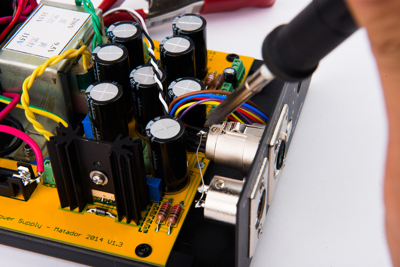
Reconnect the pin 1 chassis connection or create a new one.
And connect the audio + and audio - leads.
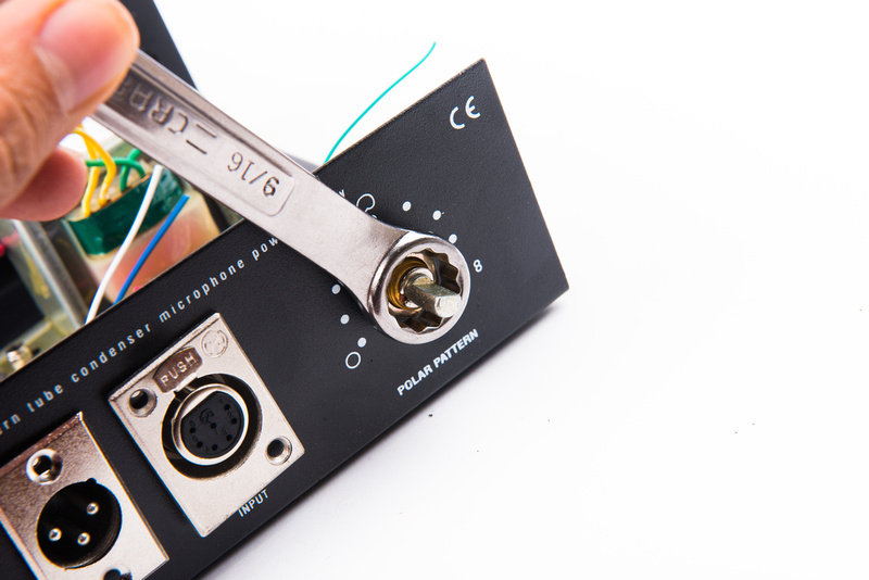
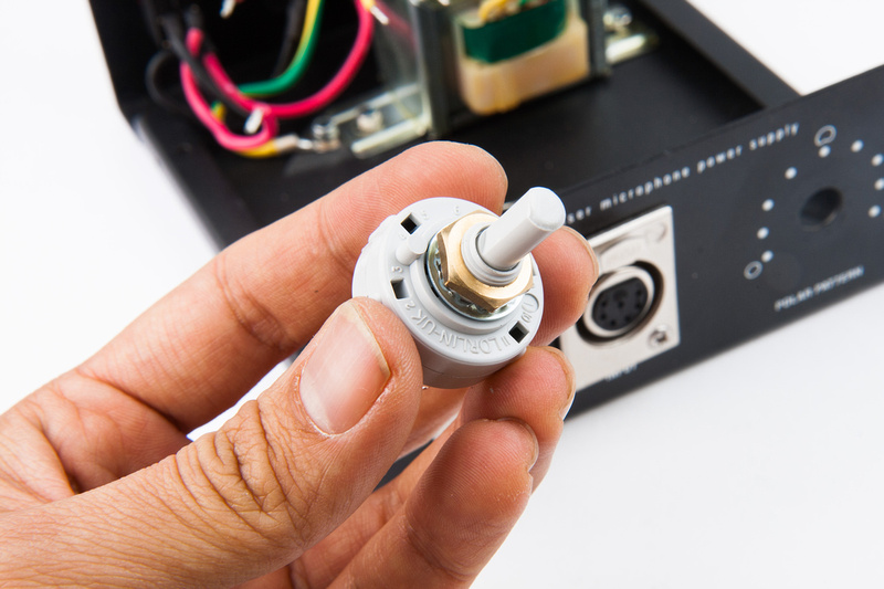
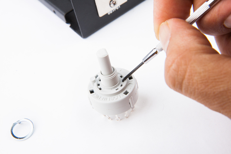
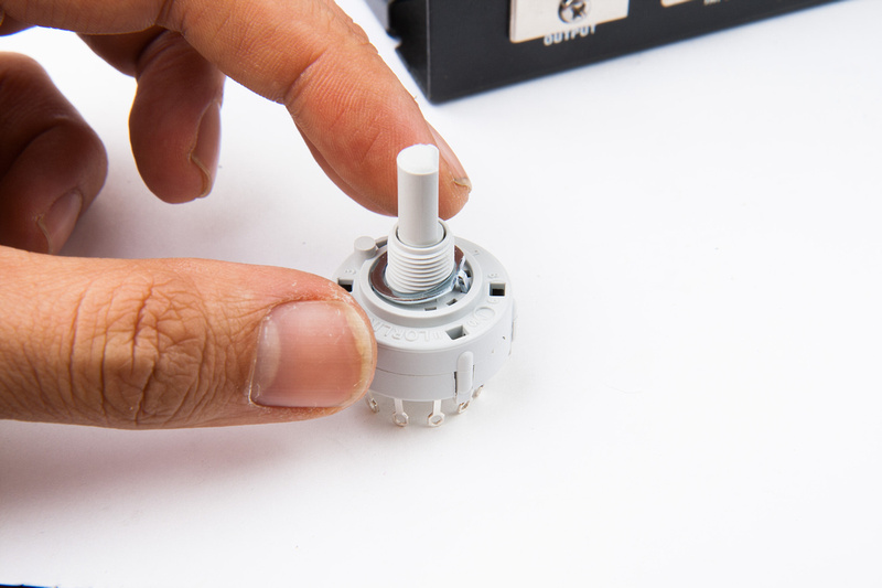
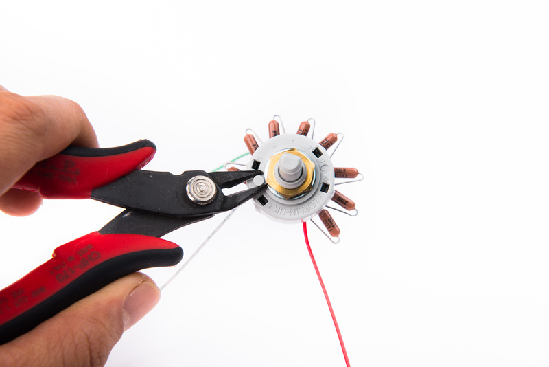
Locate the switch that we previously prepared. If using the Lorlin switch, cut off the anti-rotation key peg.
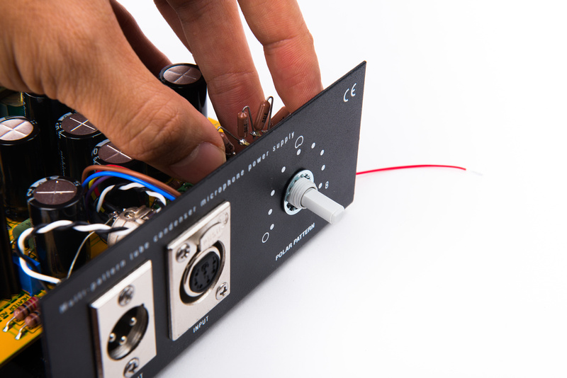
Lock washer goes on the front side of the assembly.
Followed by the nut.
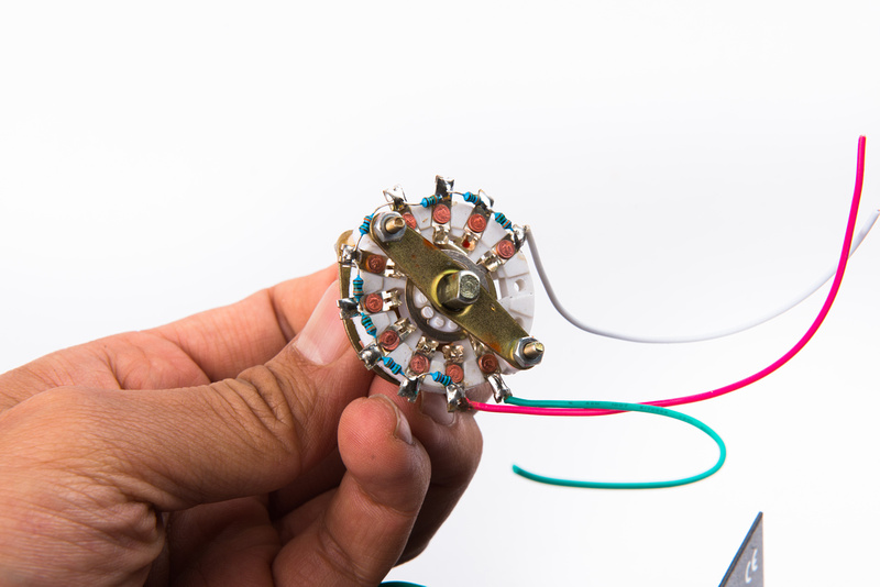
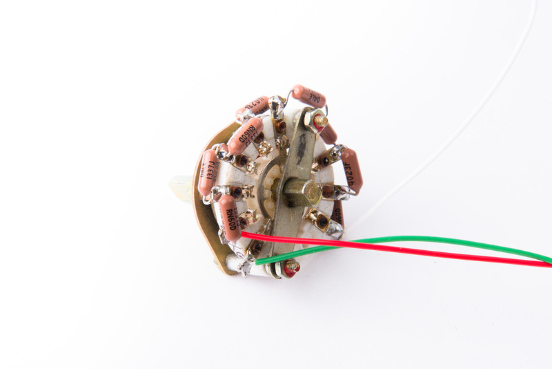
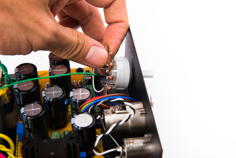
For the C12, the switch wires should be located as follows:
- outside = white
- middle = green
- inside = red
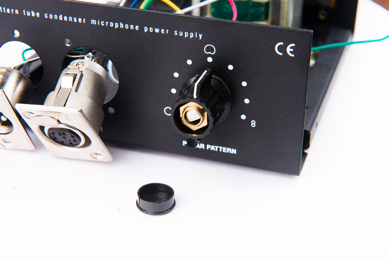
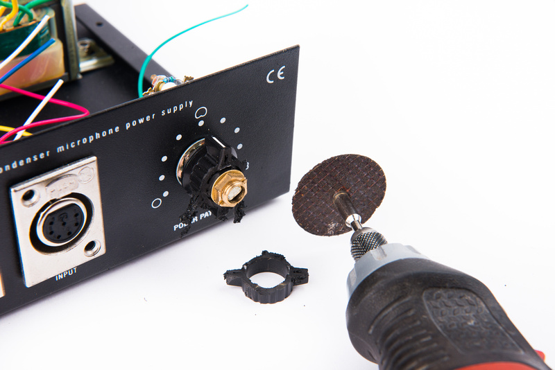
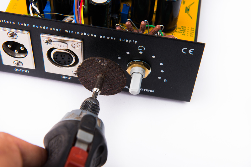
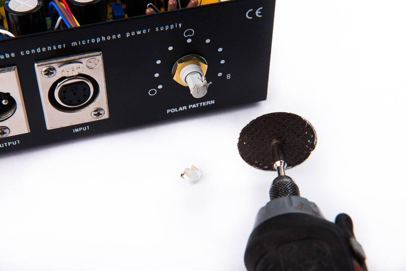
The shaft for the switch seems a little bit long for the chicken knob that I like to use, so I remove about 1/8" with a dremel cutoff wheel.
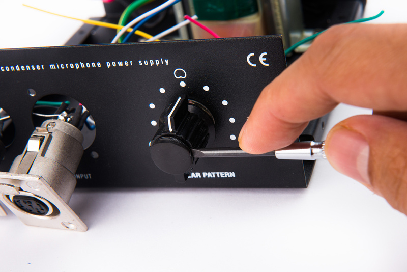
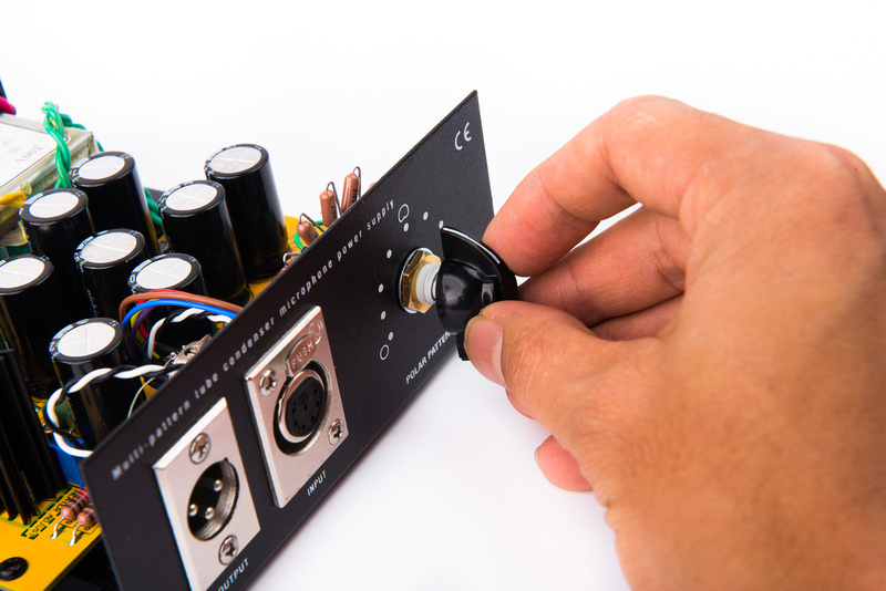
And install the pattern switch knob.
Now, the power supply is completely wired and ready for testing.
Install the 500mW fuse.
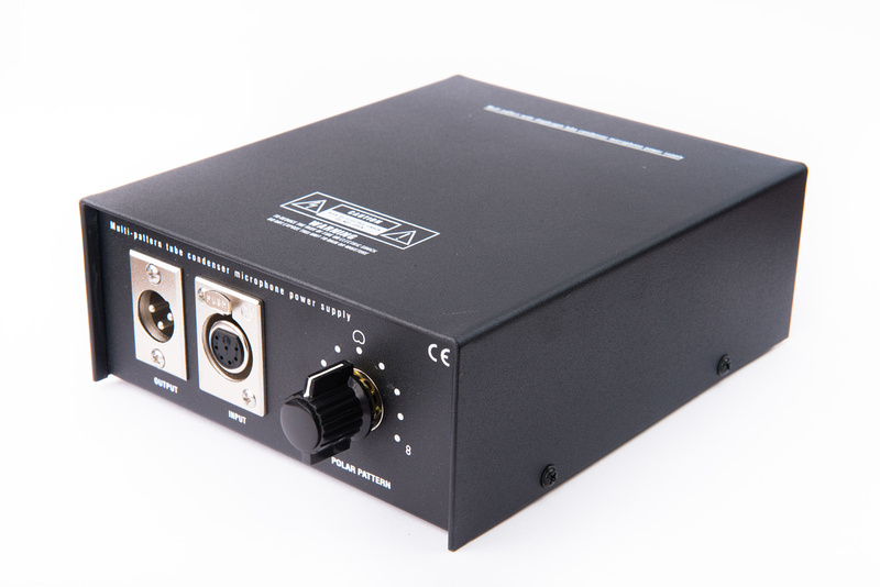
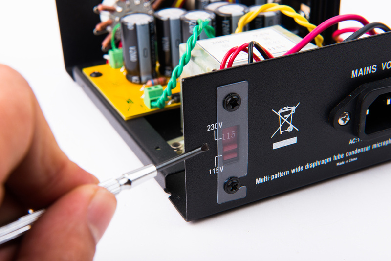
A switch on the back of the power supply selects between 230V and 115V mains voltages. Because I am in the United States, I select 115V.
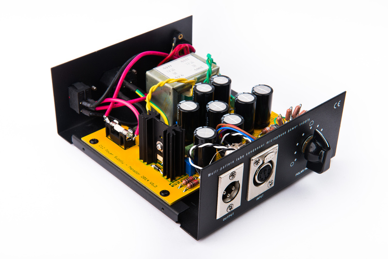
The power supply is now complete.
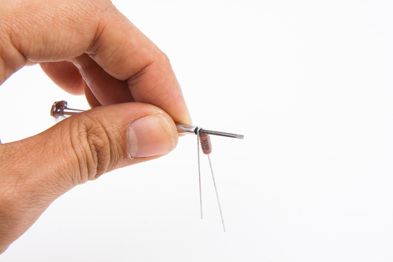
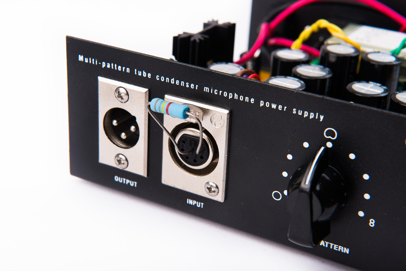
For our C12 application, a 180K 1 watt resistor will serve as a substitute for the actual microphone for initial testing. This is a much safer way to confirm power supply function than risking an actual microphone. You can place the resistor directly between pin 1 and pin 7 on the 7 pin XLR.
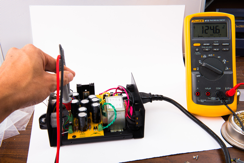
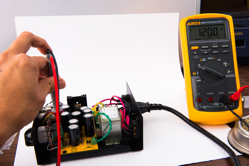
No surprises on this build, right out of the gate, we have 124.6V on the B+ which is very well centered.
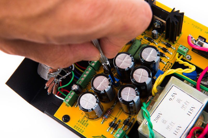
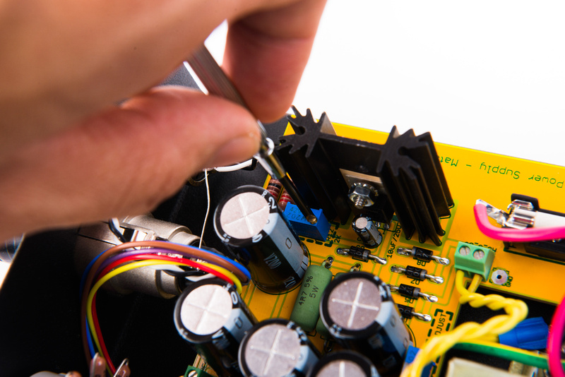
The B+ is easily adjusted to the nominal 120V by making a few turns on the B+ trim pot.
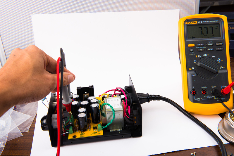
Right out of the gate, the regulated heater sits at 7.7 volts.
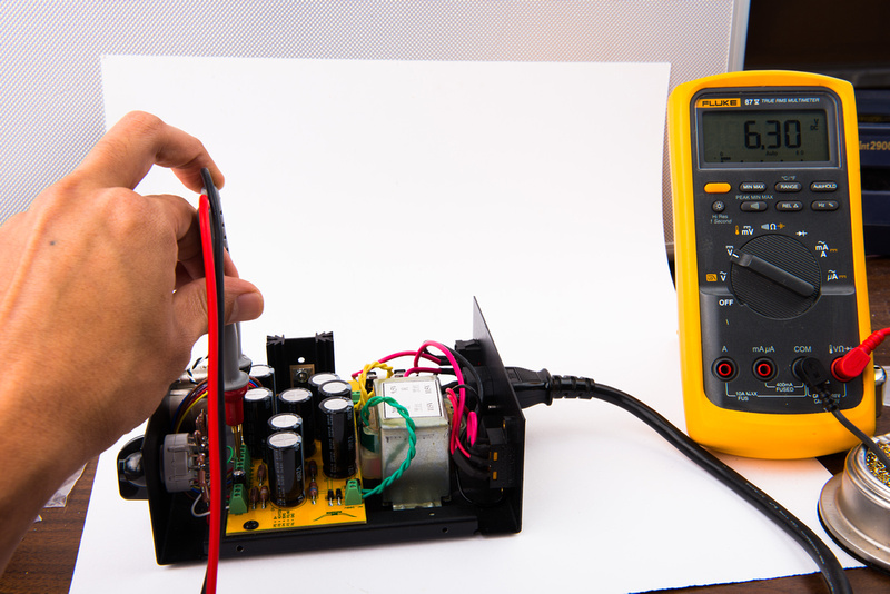
The heater trim pot quickly brings that to our target 6.3V. Depending on the cable length and wire gauge, this should be re-adjusted on the microphone later, but for now . . .
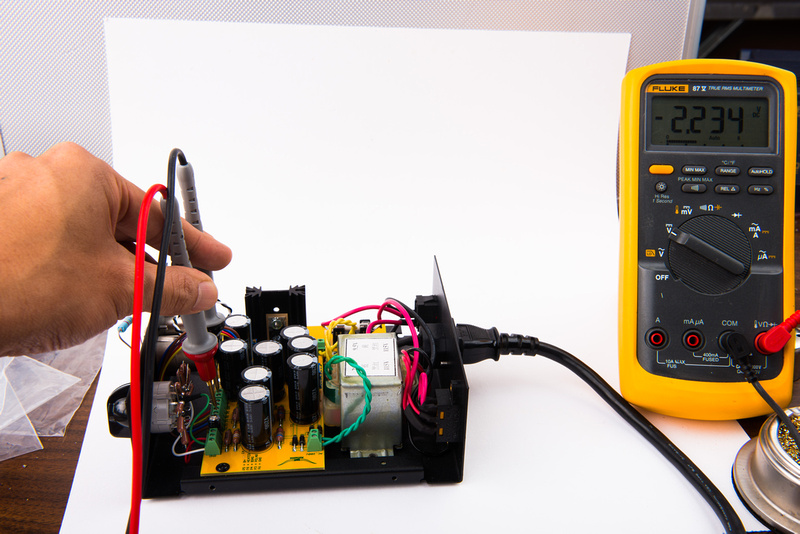
Many microphones will not use the bias output, but the C12 does. . . this will certainly need to be adjusted on microphone later, but right off, we have -2.234V.
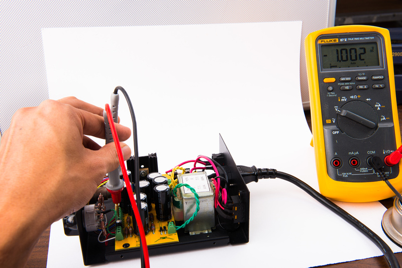
We can dial this to ~-1V for now and re-visit this when setting up the microphone.
The power supply is now roughly function tested and ready to connect to the microphone for final tweaking.


