PGA2320 Attenuation Range Issue

GroupDIY Audio Forum

Help Support GroupDIY Audio Forum:

This site may earn a commission from merchant affiliate links, including eBay, Amazon, and others.

adastra

Active member
Joined
Oct 8, 2012
Messages
32
Hello,
I've got a line level circuit, with an OPA134 feeding a PGA2320, then to a 1646 line driver.  Using arduino to program the PGA2320 and I'm finding some odd behaviour.  As I understand it, the Gain range should correlate to bytes from 0-255.  I don't want to add gain, so my max is 192 (unity).  192 works just fine, but as I attenuate, it bottoms out at 165, measuring about 45dB below unity.  When I go below 165, it immediately jumps up to about 25dB below unity and stays at that level all the way down to N=0.  Another way of putting it is that from N=0 to N=163 I get about -25dB, then at 165 level drop another 20dB and begins to increment normally. 

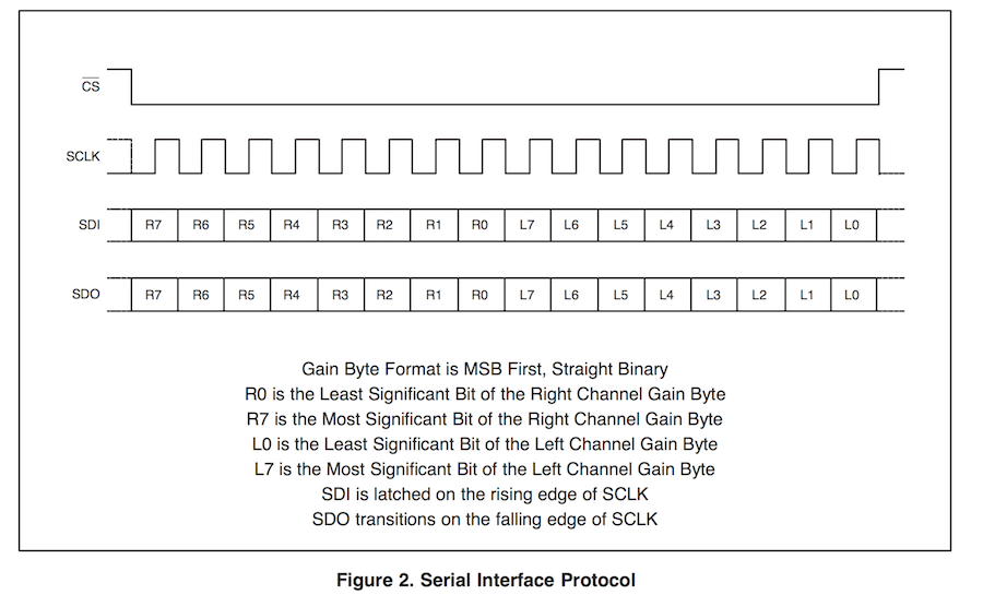
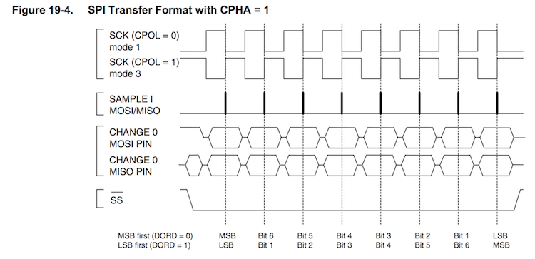
I'm transmitting SPI at 4Mhz, MSB, SPIMODE3.  In other respects it seems to respond fine to programming and sounds good, but I'm just stuck with the limited attenuation range.  Any thoughts would be much appreciated.

 
Are you sure that when you load in the value 192 (for unity gain), you're doing so for each channel, and that the timing of the chip select is correct? (look at it all on an oscilloscope.)
 
Pretty sure I'm sending to both channels (one byte each) as I'm able to set them to different levels.  I think you are on the right track with timing.  I'm going to see what I can do with that, bit of a newbie with the scope, but this is a good reason to get better.

My function is pretty much as follows:

void setVolume(byte vol){
  SPI.beginTransaction(SPISettings(4000000, MSBFIRST, SPI_MODE0));
  digitalWrite(ssPin, LOW); 
  SPI.transfer(vol);
  SPI.transfer(vol);
  digitalWrite(ssPin, HIGH);
  SPI.endTransaction();
  EEPROM.write(currentVolAddr, vol);
  Serial.println("Volume is:  ");
  Serial.print(vol);
}
 
adastra said:
Pretty sure I'm sending to both channels (one byte each) as I'm able to set them to different levels.  I think you are on the right track with timing.  I'm going to see what I can do with that, bit of a newbie with the scope, but this is a good reason to get better.

My function is pretty much as follows:

void setVolume(byte vol){
  SPI.beginTransaction(SPISettings(4000000, MSBFIRST, SPI_MODE0));

Mode 0 or Mode 3?

Also, does the SPI.transfer() function block until the transfer is complete, or does it return as soon as the word is written to the outgoing shift register? (I don't know anything about the Arduino API.)

-a
 
Upon re-examining the datasheet, I'm now using Mode0.  On your other question: it appears the data returns immediately on using the transfer function.
From the Arduino SPI API:
byte SPIClass::transfer(byte _data) {
  SPDR = _data;
  while (!(SPSR & _BV(SPIF)))
    ;
  return SPDR;
}
Which I think means essentially, set byte as data, while status and interrupts aren't busy return data.

One thing I found on my scope is that I seem to be sending 2 consecutive clock cycles with one byte in each.  I guess I need to combine them into a 16bit word and send that within 1 clock cycle. 

I've got a friend loaning me a logic analyzer later in the week so I think that will help me see what's going on a little easier than my 2 channel scope.
 
adastra said:
Upon re-examining the datasheet, I'm now using Mode0. 

Revisit the PGA2320 data sheet. Look at Figure 2:

PGA2320_SPI.png


The first rising edge of the SPI clock captures the first bit, which was asserted half a clock period before.

This corresponds to the ATMega's (the microcontroller in the Arduino) Mode 3 SPI:

ATMegaSPI_Mode1_3.png


Notice the sampling edge, and also remember that you are sampling (in the PGA2320) the SDI signal, which is an output from the ATMega. In the SPI parlance, that signal is called MOSI, for "Master Out Slave In."

On your other question: it appears the data returns immediately on using the transfer function.
From the Arduino SPI API:
byte SPIClass::transfer(byte _data) {
  SPDR = _data;
  while (!(SPSR & _BV(SPIF)))
    ;
  return SPDR;
}
Which I think means essentially, set byte as data, while status and interrupts aren't busy return data.

OK, so the _data argument is loaded into the SPI Data Register, which loads the shifter and the SPI hardware starts working.  Then the code spins on the SPI Interrupt Flag, waiting for it to go true, which indicates transfer complete. The act of reading the SPI Status Register has a side effect, which is to clear that interrupt flag.

Finally, it reads the SPI data register. Remember the SPI port shifts out your _data argument on MOSI and at the same time shifts in whatever is on the MISO ("Master In Slave Out") pin. After the shifting is complete, the received word is sitting in the SPDR, so the function reads that register and returns that value.  If you don't care about the read word you can ignore the return value.

One thing I found on my scope is that I seem to be sending 2 consecutive clock cycles with one byte in each.  I guess I need to combine them into a 16bit word and send that within 1 clock cycle.

The ATMega's SPI port can only handle eight-bit words, so you need to do two SPI.transfer() calls, one first for the right channel level and followed by the left channel level. And even though the PGA2320 data sheet shows a continuous clock and sixteen bits sent in one transaction, it is perfectly fine to do the two 8-bit accesses, which will have some short delay between the two bytes. If you look again at the SPI Mode 3 timing, you'll see that the port idles SCK high. The clock goes high on the 8th bit so the slave can clock that bit in, and then it stays high. When it goes to start the second byte, the clock will go low as the first bit of that second byte appears on MOSI, and then it goes high so the slave can capture it.

I've got a friend loaning me a logic analyzer later in the week so I think that will help me see what's going on a little easier than my 2 channel scope.

Yeah, they're handy. Set the analyzer to trigger on the falling edge of the slave select.
 
I ended up writing my own spi routines and used them in several designs because I found the stock SPI firmware difficult to get good results with.

May be a personal problem with microchip silicon (or my self-learning how to code).

JR

 
Well, I feel foolish but also quite happy to have a working circuit.  My problem was electrical, just sloppy breadboarding with a poor ground connection at the input.  With that fixed, I've got full and reliable volume control using the simple function I started with.  Also back to Mode3, although Mode0 seems to work just fine as well.  I suppose timing issues probably become more critical as the bus has more going on. 
Thanks John and Andy very much for your comments.  Cool chip, sounds quite transparent and even without ZCEN its very smooth and quiet on volume transitions. 
 
adastra said:
Well, I feel foolish but also quite happy to have a working circuit.  My problem was electrical, just sloppy breadboarding with a poor ground connection at the input.  With that fixed, I've got full and reliable volume control using the simple function I started with.  Also back to Mode3, although Mode0 seems to work just fine as well.  I suppose timing issues probably become more critical as the bus has more going on. 
Thanks John and Andy very much for your comments.  Cool chip, sounds quite transparent and even without ZCEN its very smooth and quiet on volume transitions.

Glad you got it working. The parts work as advertised, and the matching between left and right across the entire attenuation range makes them attractive for critical applications. Certainly they're better than cheap stereo pots.

We have a pair of KRK self-powered studio monitors hooked up to the TV, and since the TV's audio output (digital, actually) doesn't follow the volume control, I built up a little box based on the PGA2320 so we could control the volume from the couch with an Apple gumstick IR remote. Works like a champ. See here. At some point I suppose I'll add the firmware and the schematic to that blog post.
 
Thanks again Andy.  I had a feeling I was overthinking it... 

Cool project, I have a similar setup with Apple remote controlling my Sabre32 DAC in the home hifi.  I'm a big of Arduino because it just lowers the barrier of entry into uC programming so much.  So many little breadboard circuits and libraries out there.  I'm trying to go a little deeper these days and understand under the hood what's actually happening, cut down on my verbosity etc.  Typically I switch to a Teensy3.1 when a project is ready for prime time.  Much smaller and faster than any arduino but most of the code is the same.


Latest posts

Back
Top