Inductance/Capacitance ratio in LRC EQ circuits

GroupDIY Audio Forum

Help Support GroupDIY Audio Forum:

This site may earn a commission from merchant affiliate links, including eBay, Amazon, and others.

Matt C

Well-known member
Joined
Apr 30, 2012
Messages
235
Location
Saint Paul, MN, USA
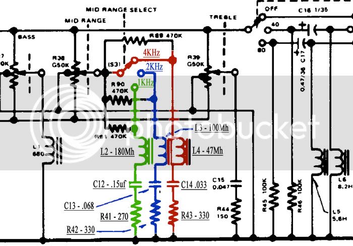
A question I've been wondering about while looking at the Yamaha PM1000 EQ circuit, although my question is more general:

Looking at the series LRC filter shown below, I'm wondering about the reasoning for choosing these particular pairings of inductors and capacitors.  For any given center frequency there are many combinations of values that will get the job done, so why settle on one instead of another?  I know changing this ratio changes the Q factor, but we can also adjust the R value to compensate.  Does this in turn affect max boost/cut? What are the trade-offs we're looking at here?

PM1000EQSchematic.jpg
 
  I think you have all the right questions, or most of them... To answer them you could just run a few simulations and compare Q factors, values and max gain/atten.

  One other factor is size/costs, bigger inductors are more expensive and might not fit the space they have to work with (depending on project specific)

  If you want to get to exquisite, higher R values add noise, so you rather avoid that, but in the level EQs usually work is not really a problem as the impedance and noise levels are not even close to find each other.

JS
 
Matt C said:
Looking at the series LRC filter shown below, I'm wondering about the reasoning for choosing these particular pairings of inductors and capacitors.  For any given center frequency there are many combinations of values that will get the job done, so why settle on one instead of another?  ....

There is a mathematical relationship among the three components for the optimum response. You can surely change the values for the same frequency but that is obviously not the only factor in the design.
 
The answer is the Q of the resonant circuit. This is given by 2*PI*f*L/R where f is the frequency, L is the inductance and R is the total circuit resistance in the RLC loop. Note that this not only includes the dc resistance of the inductor but also any other resistance in the loop. You often see series resistors in the RLC loop in classic EQs like the Pultec to alter the Q of the circuit.

Cheers

Ian
 
Start by deciding what load your *amplifiers* (or interfaces) can drive. 50K? 2K? 100r? One Ohm??

For audio bumps the Q is usually near "1".

So your reactances will need to be round-about the amplifier happy impedance, at the center frequency, and loaded with an R of about that impedance.

So. We want a 50Hz bump in a tube circuit of 50K Ohms. We need a 160 Henry coil. Hmmmm.... not a real common value. If found, it is a huge lump and very expensive.

OK, we get a Crown DC300a, drives 10 Ohms in its sleep. 32 milliHenries is a small coil, tho less-small if we want DCR much lower than 10r. But now the cap is 320 uFd, a huge lump which is likely to be low-tolerance.

It looks like a happy-zone for impedance is around 500-1K. However the lo-cost opamps may force you to 2K, or even 10+K if you plan to drive several tanks with one opamp. OTOH simulated coils can be cheaper than real-coils, and take some of the curse off high impedances.
 

Latest posts

Back
Top