How to adjust high-mid frequencies of tube preamp?

GroupDIY Audio Forum

Help Support GroupDIY Audio Forum:

This site may earn a commission from merchant affiliate links, including eBay, Amazon, and others.

BluegrassDan

Well-known member
GDIY Supporter
Joined
Mar 17, 2009
Messages
508
Location
Elizabethton, TN
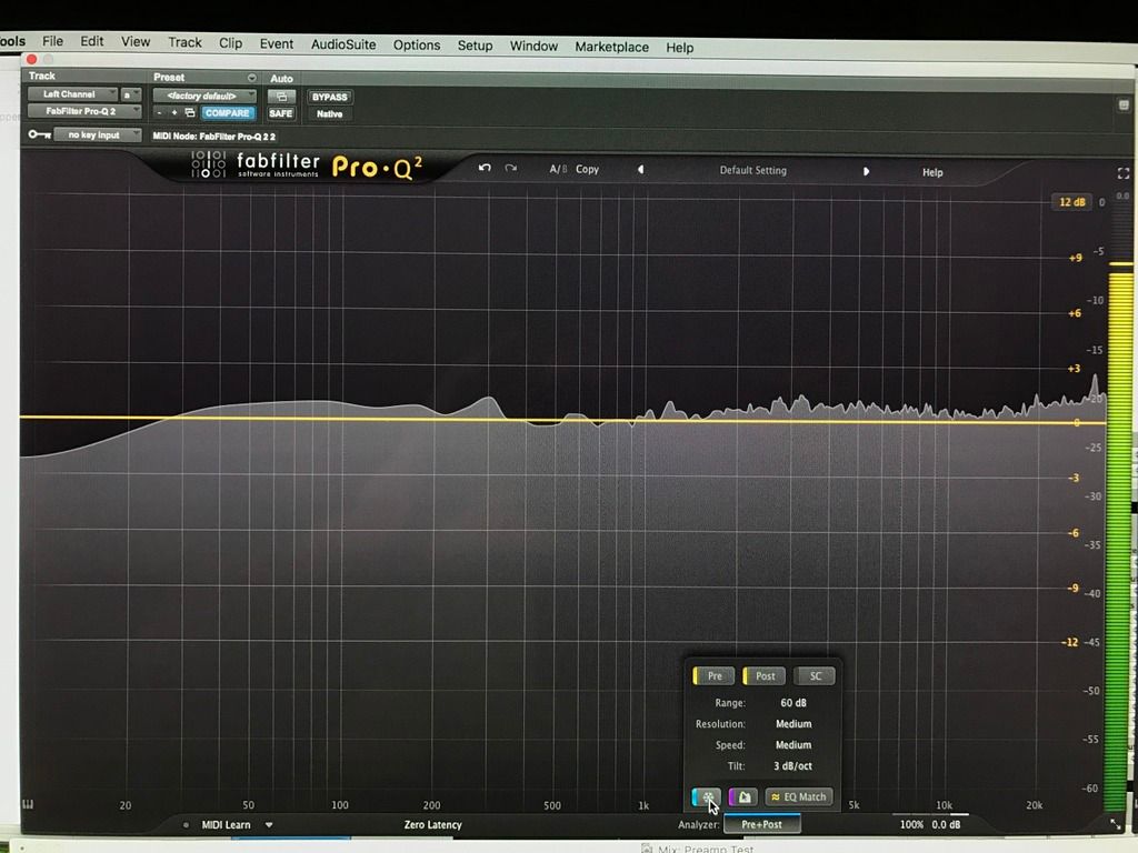
I just built a two-channel tube mic preamp based on Scott Hampton's schematic. Which components should I adjust/replace in order to decrease a slight bump at 2-3k? Would like to attenuate this area around 1-3db.

(The only difference from this schematic is that I have added 0.015uf bypass caps to C1-C5, and I have added 330 ohm grid stoppers to pins 2 and 7 of all four tubes.)

Thanks in advance.

Schematic:
https://www.dropbox.com/s/eb7b88mltuvfju3/fig1.jpg?dl=0
 
There is no obvious reason why that circuit should add a bump at 2-3k. To track it down you should divide and conquer. I suggest you repeat the test without the transformers and see if it is still there.

Cheers

Ian
 
  It's more likely to be the jensen bringing the problem, better quality doesn't mean no load is needed, you still need to load them properly and usually inputs are more of a problem with this. Also, you might be missing some bigger bump over 20k, you should try it without the transformers and see if the bumps are still there, if there is no bump add one transformer at a time. Once you identified the problematic one add a zobel network to compensate. It's better to do so using an square wave and a scope rather than noise and frequency plot as the effect is much easier appreciable in the time domain.

JS

PS:  If you don't have an scope and you are shooting in the dark, jensen probably has some suggested values for that transformer and you could start from there.
 
Something strange about that plot.  Maybe settling time.  I've never measured any amplifier with such a rough response.  It may be overloading, which will look like that. 
 
emrr said:
Something strange about that plot.  Maybe settling time.  I've never measured any amplifier with such a rough response.  It may be overloading, which will look like that.

It's probably measured instantly with noise, not a proper transfer response...

BluegrassDan said:
By loading, are you simply referring to the resistor value between the secondaries of the input transformer?

(Thanks so much for the help, guys.)

Not just a resistor, a Zobel network. In parallel with that resistor a series RC tuned for the particular transformer, you have to properly select the 2 resistors and the cap value to obtain the best response. There might be recommended values to start to play with.

JS
 
> probably measured instantly with noise, not a proper transfer response...

+1 to you.

-1 for measuring amplifiers this way.
 
PRR said:
> probably measured instantly with noise, not a proper transfer response...

+1 to you.

-1 for measuring amplifiers this way.

...why?

JDB.
[working on open source THD/IMD-measurement software; the radio engineer in me wants to add PN-based freq/phase-response estimation. Have done so for limited scale acceptance testing of audio modules before; now would be a good time to learn why this would be a Bad Idea (apart form the usual caveat that it only really works when the channel is fairly linear)]
 
For clarification, I'm a newb at building stuff. My only tools available for measuring the frequency response are simply running my signal generator in Pro Tools and my own ears (which I can hear the mid-high presence and scooped out mids - all very subtle, but I know what I want to hear with this preamp).

Let me play around with the transformers and see what's happening. Thanks so much for the help.
 
jdbakker said:
...why?

JDB.

Cause...

Proper transfer measurement software do it comparing the original signal with the processed through the device under test (DUT from now on) instead of measuring just a processed signal that is supposed to be flat.

  In this procedure you connect two outputs (or one split two ways) one directly to an input and one through the DUT, then from the DUT to a second input, config the software to know which is the reference and which the DUT. Usually it measures amplitude, phase and correlation, plus you can do THD, noise, IR, etc.

  Here are some useful software to do so, there are cheaper or even free ones, I cant remember the one I used for this kind of task, it was pretty useful in the free version but mac only.
http://www.rationalacoustics.es/smaart-v-8/
http://mhsecure.com/metric_halo/products/software/spectrafoo.html
http://www.faberacoustical.com/apps/mac/electroacoustics_toolbox/
https://www.roomeqwizard.com

  Same software can be used to measure room acoustics and reinforcement systems, different setup of course... Speaker and mic involved inside what we call DUT

JS
 
joaquins said:
That is, respectfully, an answer to a very different question.

I'm very interested in theoretical/practical reasons why measuring frequency/phase response by emitting a (controlled) PN sequence and cross-correlating the received signal with the original, as is very common in RF channel sounding, would run into problems in audio systems (if one takes clipping/non-linearities into account). As noted I'm writing software to do such measurements, which I hope to release as an open and more automatable alternative to RMAA and the like. One of the reasons for doing so is the user would know exactly what's happening under the hood, which is one of the common issues with RMAA and several of the tools you link to.

In other words: what is the cause of the wobblies in the frequency response plot shown earlier?

JDB.
[I could imagine things like uncorrelated measurements, jittery sample clocks, nonlinearity, improper FFT windowing and/or insufficient SNR playing a role, but I would like to know]
 
I experimented with a few capacitors and resistors. The sound of a .001 µF cap with a 75K resistor  might just do the trick. Take a listen and let me know what you think.

( forgive the sloppy playing. I was in a hurry.)

https://www.dropbox.com/s/21sgntjveuy539k/KM84%2C%20Telefunken%2C%20no%20zobel.wav?dl=0

https://www.dropbox.com/s/3w1qnewqe9if3fh/KM84%2C%20Telefunken%2C%20with%20zobel.wav?dl=0
 
I would accept a hiss (or pseudo-random) test IF it gave smooth flat response on a known-smooth/flat signal path.

Tests aimed for room-response often lack the accuracy we like in amp-response, because rooms are such inconsistent things. I have got good smooth room-responses by averaging for many minutes; this is rarely called-for or useful in rooms. I have not closely pondered speed of random noise measurement, or what pseudo-random advantages are.

Anyway-- when I see a amplifier response as lumpy as that in reply #2, I don't see few-dB accuracy.

There is a sound-card tool which gives wonderful curves (I believe sweep-tone).
 
BluegrassDan said:
Back to my original question. How do you think the preamp sounds now with the RC network added after the input transformer (two posts above)?

Will this RC potentially change the signal phase?

  It should dampen the self resonance of the transformer, mitigating the bumps and corresponding phase misbehavior. If there is a problem with the transformer self resonance this could potentially solve it, improving the sound of the signal path.
  There is a funny story involving sir Rupert and Abbey Road Studio, where he was called because a few channels on a mixer were sounding harsh and he found the problematic channels had a bump around 50kHz since they where missing the transformer's Zobel networks. The story say, here he concludes the bandwidth should be greater than 20kHz since a 50kHz problem was perceived. I don't know if I should said this but Mr Walker (RIP) told me about this story saying Rupert had the right conclusion for the wrong reasons, arguing the slight effects under 20kHz of the 50kHz problem has more influence than the actual 50kHz bump. That plus the known issues if the gain blocks can't handle the signal generating IMD. This is a discussion between two heavy weights, all we can do is design as smooth as possible to about 50kHz and call it a day, anything over that should be filtered, anything under that should be nursed.

jdbakker said:
That is, respectfully, an answer to a very different question.

I'm very interested in theoretical/practical reasons why measuring frequency/phase response by emitting a (controlled) PN sequence and cross-correlating the received signal with the original, as is very common in RF channel sounding, would run into problems in audio systems (if one takes clipping/non-linearities into account). As noted I'm writing software to do such measurements, which I hope to release as an open and more automatable alternative to RMAA and the like. One of the reasons for doing so is the user would know exactly what's happening under the hood, which is one of the common issues with RMAA and several of the tools you link to.

In other words: what is the cause of the wobblies in the frequency response plot shown earlier?

JDB.
[I could imagine things like uncorrelated measurements, jittery sample clocks, nonlinearity, improper FFT windowing and/or insufficient SNR playing a role, but I would like to know]

  You're right, I thought I was answering to the OP who wouldn't really get to the theory behind it I guess.
  The normal approach is to align it in time (time intercorrelation peak would indicate how much time is needed to align both signals), then the FFT is applied and the transfer function between the two is estimated. The measurement's reliability is given by the intercorrelation (in frequency domain) between the two signals, if too much noise get's in the way the intercorrelation will decrease at the problematic frequency, this results in confident measurements for some areas of the spectrum and not others.
  Thinking about sound reinforcement makes easier to picture the problematic areas and timing issues, when you measure the sub woofer the intercorrelation starts to decay once over the x-over frequency as the environment and system noise gets much greater than the signal, also the delay because the speed of sound is different from the floor subs than from the hanging coils and usually needs some compensation. Of course for that kind of measurements the averaging and smoothing is much higher, usually starting from very smoothed, small average to get the first approach and alignment between the different speakers ways to a much averaged, less smoothed to fine eq tweaking and conflicting peaks removal.
  As PRR said it's not the same test but the same tools could be used very effectively. When measuring a mic preamp for instance you expect very stable and low noise measurements, you probably won't even be looking the intercorrelation all the time as you do with rooms, averaging and smoothing could be quite small or non existent, increased averaging of course would provide more stable and precise readings, not necessary with greater exactitude.
  The other hidden variable is the source signal, doing the transfer function you completely eliminate the source as a variable and sometimes music is used, as you have the sound getting out of the speakers and people already in the beach where the show takes place later. You still need content on every frequency and this is a compromise you sometimes have to take for this reasons or just for confort depending on how demanding the task is. While measuring equipment music makes no sense, as you don't need to be hearing what's going on, but still you can get away with a much less refined "random" signal than using the FFT directly on the turn around signal. I don't even know how well you can measure phase response in that way.
  Note that RF measurements are usually much less precise than audio, marketing guys in this industry would kill a puppy for 0.1dB!
  This is getting way too long, feel free to PM me about this, I'm interested. Also you could start a topic on the chamber I guess to discuss this.

JS
 
jdbakker said:
I hope to release as an open and more automatable alternative to RMAA and the like. One of the reasons for doing so is the user would know exactly what's happening under the hood, which is one of the common issues with RMAA and several of the tools you link to.
Interesting. Can you be more specific about it? What are the "common issues" with RMAA? And how yours would be different?


[I could imagine things like uncorrelated measurements, jittery sample clocks, nonlinearity, improper FFT windowing and/or insufficient SNR playing a role, but I would like to know]
I would think it's all these factors that make FFT-based measurements somewhat fiddly.
You do an analog sweep, you have to care about BW, linearity and noise, speed also.
In FFT-based, you have have to take care of windowing, jitter, and how reliable/repeatable/consistent is the test signal, and also how the signal reacts with the DUT. I believe you've noted that the initial transient seems to sound different every time. So you never get two successive measurements to superimpose perfectly (well, at least as well as two successive sweeps).
It's generally not a big deal, but I've seen consistently people doing several measurements just to make sure they were consistent (or the software does it automatically), so the advantage of shorter measurement time is lost against confidence.
I believe there are more traps for an untrained user in FFT-based than in sweeps.
 
I think I figured it out. V2 of my left channel was way overbiased, causing some weird harmonic smearing in the upper mids. Tailored it back to linear and things tightened up.

Also, added a low shelf RC network after the first gain stage and switched attenuator. That made everything amazing!

Here is a new audio sample, 24bit/88.2k. Curious to know what everyone thinks.

https://www.dropbox.com/s/3oz462gzkg6d39u/Danny%20Boy%2C%20KM84%2C%20Low%20shelf%20AMAZING.wav?dl=0

Thanks for all the great input.
 

Latest posts

Back
Top