[BUILD] fripholm's TG1 Zener Limiter boards - support thread

GroupDIY Audio Forum

Help Support GroupDIY Audio Forum:

This site may earn a commission from merchant affiliate links, including eBay, Amazon, and others.

fripholm

Well-known member
Joined
May 26, 2013
Messages
349
Location
DE
IMG_7840.JPG


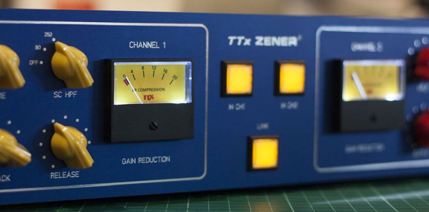
As requested, this is the support thread for my Zener Limiter boards. They are not available. Please don't ask for gerber files.

Black Market thread: FS: PCBs for TG1 Zener Limiter
Manual, updated 2019/09/30 (board revision v2.5): TTx Zener Guide

The guide includes BOM, schematic, an optional DIY PSU, general build and fine tuning instructions, a front panel design etc. - I will update that archive occassionally, when issues come up that I think are worth to be included or need to be corrected. Please make sure you have downloaded and read the most recent guide before posting here for support.

Feel free to also share stories and/or pictures of your builds, finished or while still in progress :D
 
Last edited:
I will start off this thread by replying to orangechili's post from the Black Market thread: https://groupdiy.com/index.php?topic=65505.msg838542#msg838542

I built both boards with a 22ohm resistor from the output + to the primary high on the output transformer. I may up the resistor value and see if that helps. It's like a big jump near the end of rotation on the output and input pots.

Then there's the meter that basically stays put after getting hit with compression...

What's hard is I have the same issue on both boards.

hmmm, none of my builts have showed the issues you describe.  :(

Regarding the big volume jump, does this happen, when the unit is in bypass or with the compressor engaged? The I/O pots should have no function when in bypass - if they have, some of the wiring in the bypass section may be wrong. I've just checked with the guide, that the drawings are correct and yes, they should be.

Can you hear the compressor's release action when compressing audio or isn't it releasing at all like the meter? Do you have an oscilloscope to check a few voltages while compressing audio?
 
After further examination I believe the compression circuit in both channels is not working right. That may explain the meter weirdness. THD and bypass seem to work decent, the loud rise of volume pops was just me talking into a mic and it clipping in comp and limit modes with the controls cranked...

I don't really hear it compressing much on either channel. As I raise input and output controls the volume just rises, not really hearing compression although the meter stays stuck and dimes after signal is inputed in comp mode . I'm gonna go through the wiring in the compression circuit again(rotary switches, etc)
 
Checked the mode, sc high pass, attack and release off board wiring and all correct according to the diagram in the guide. I was hoping for there to be an issue in the mode wiring which seems like it would cause the issue I'm experiencing but no luck...
 
I should mention I used a standard pot for the release control without the auto release function. I also connected the input transformer secondary ground to the open ground point where the open auto release pads are. It all returns to chassis ground(verified with my continuity meter)

I'd be curious to see if others have built these and are having a similar issue
 
The release pot is in series with R51 that goes to ground when auto release is OFF or not used, like in your case. When this connection doesn't exist, the control voltage doesn't have a path to ground and gets stuck - which might explain your issue.

Check if the middle pad of the auto release is jumpered to ground next to it.
 
The middle auto release pad does not jumper to ground. I was probing around looking for an open ground point on the board when I found the open 'auto release pad'. I'll see if moving the Input Tx's secondary low wire to a different ground point fixes the issue.
 
I moved the wire to another ground point. Still the same as before. It seems like it's barely compressing at all while looking at my daw's meter. I notice a tiny bit of peak reduction in the limit mode with the input and output controls all the way up.
 
No, it's not the input transformer wire that needs to be moved. The middle pad of AUTO RELEASE (which is the ground side of R51) needs to be connected to ground.
 

Attachments

  • cl.jpg
    cl.jpg
    31.6 KB
Ok, thank you for that! The meter now works as expected!!! I'm going to start going through the calibration process. I'm noticing a ton of distortion in THD mode on both channels. If you or someone has a video of one of your units working that would be helpful as well.
 
Any recommended values for R86 and R87 for use with a 4:1 input transformer would be greatly appreciated as well! I'm noting quite a bit of  volume reduction in bypass modes with the 4:1 step-down
 
Just when I was about to ask some questions in the BM  thread you opened this build thread! Fantastic! Thumbs up!

I'm in the process of working on dual channel TTx TG1.
I've stuffed boards except putting resistors that need calibrating. I've omitted hold control but have resistor in place of where it should go if basic compression works as it should and I plan to add it later. My build has no bypass and no input transformer - I permanently connected input to the board and jumpered bypass switch pads in permanent ON position. I have relay board near in/out connectors that will handle bypassing.

Now my issue is that both channels distort heavily in any mode. No compression at all! I've triple checked wiring (especially around HPF and Mode switches) and it seems okay. Meter is dead also.
Then I went to cross reference my build with schematics from Fester's TG1. I checked voltage on D2 and D4 input and it's around 13vdc. In Fester's that would be T_B. and T_C and they should be 10.6vdc.
Also, on Q1 emitter there's 6.8vdc (don't know what should expect here)
I had no more time to investigate further...

It's Murphy's law that you find your mistake just after asking for help!
I found what I did wrong - diodes D6 and D7 were orientated wrong. Now it's working almost as it should. I hear compression and limiting. THD mode is really distorted! I was expecting less distortion but it's cool.
I still have to go through calibration. Drivers for my oscilloscope are quirky and I have to fix that in order to go further.
But before I must say that I hear a lot of white(ish) noise when unit is compressing. Maybe it's too much compression that's pulling out this noise. I'll get back to that after I calibrate.

I'm still running my unit with unbalanced input. Is there anything I should change if I decide to leave it unbalanced? Maybe add an input pad?
If I decide to use 2:1 transformer what impedance should I go for?

Fripholm, during the hunt for error a BIG BIG help would be if you could publish pcb's silkscreen layer or hi-res photo of the board so we can all read component designations. Once the board is stuffed it's almost impossible to find certain components since they cover the silkscreen (yeah... I forgot to scan the board before stuffing... dohh me...)

:)

Luka
 
orangechili said:
Any recommended values for R86 and R87 for use with a 4:1 input transformer would be greatly appreciated as well! I'm noting quite a bit of  volume reduction in bypass modes with the 4:1 step-down

I've already answered that in the Black Market thread, yesterday:

try 1.8k and 2.2k for R86 and R87, respectively.
 
OK, I've updated the manual with infos about omitting the Auto Release function and added the board's silkscreen layer for reference. Just re-download the ZIP archive linked  above in the first post.

Recently I have finished upgrading my stereo unit with 24-way stepped attenuators for input and output (Elma type 04). The resistor values I'm using for the switches have been added to the guide as well.


shot said:
I'm still running my unit with unbalanced input. Is there anything I should change if I decide to leave it unbalanced? Maybe add an input pad?

If you have Fester's schematic, you could use the resistor values from the original for the input pad. It gives about 9~10dB attenuation. The component numbers are R78, R79, R80 and cap C24, which translates to R1, R2 and C3 on my board. You just have to connect Fester's R80 in series to my C3 (changed to 150p) for the same 'frequency characteristic correction' as there's no equivalent for the original R80 on my boards - although the correction itself is still there.

Using the input pad should also lower the amount of distortion. However, don't expect THD mode to be subtle - it's brutally awesome 8)

 
Really nice,
I was waiting for this support thread since I bought my pair of TG1 pcbs. Now I'll be more confident on starting building it up.

Thank you !
 
Hi Fripholm,

Thank you so much! Sorry I missed your answer in the BM thread
Quote
try 1.8k and 2.2k for R86 and R87, respectively.


That definitely made it louder in bypass mode with the 4:1 input TX. I'm still about 3db quieter in my daw though. Is there another value(s) I can try to gain that 3db back? Getting closer!

I'm trying to use s(m)exoscope to do the CV fine tuning but notice no change in the waveform view when turning the trimmer. I've tried adjust the waveform view specs etc. Is there a good oscilloscope software someone can recommend for a mac?

 
orangechili said:
That definitely made it louder in bypass mode with the 4:1 input TX. I'm still about 3db quieter in my daw though. Is there another value(s) I can try to gain that 3db back? Getting closer!

I'm trying to use s(m)exoscope to do the CV fine tuning but notice no change in the waveform view when turning the trimmer. I've tried adjust the waveform view specs etc. Is there a good oscilloscope software someone can recommend for a mac?

Maybe you're losing dBs through your output transformer? Is it a 1:1? How much quieter is the signal when you just connect a cable from output to input on your audio interface?

R86 and R87 just form a simple voltage divider. I'd recommend you temporarily try a 5k trimmer or pot in place of R86 and R87. Adjust the trimmer/pot for unity gain, carefully remove it and measure both halves - find resistors with the closest measured values; there you have your new R86 and R87.

S(m)exoscope should get you close enough. Set the TIME knob at 0.002 or even lower.

AFAIK, MOscilloscope can't be set to display a longer timeline.


Attachments

  • smexoscope.jpg
    smexoscope.jpg
    31.4 KB
Thanks for the oscilloscope tips guys! I managed to use the trial version of blue cat oscilloscope multi and get the CV tuning calibrated with that in the loop mode.

The output tx is 1:1 600ohm:600 ohm
My input tx is 10k:600 ohm

I'll try the 5k trimmer and report back what values i get. I figure it will be helpful for anyone who wants to try a 4:1 on the input iron.
 

Latest posts

Back
Top