PCBs for 1176-flavoured FET compressor w/ opamps - (almost) no wiring

GroupDIY Audio Forum

Help Support GroupDIY Audio Forum:

This site may earn a commission from merchant affiliate links, including eBay, Amazon, and others.
pstcho said:
for that i see, only the ne5534 or the THAT 1646 could the "noise genrators "

The problem is that in a FET compressor the signal level has to be extremely low (<<100mV) at the gain reduction FET for it to remain in its linear region. Otherwise it would distort heavily.

Your real "noise generator" in this case is the thermal noise added by resistor R10 (10k) and the input pot which in the worst case adds another 2.5k at its -6dB position. Both of these resistances account for about -112dBu of noise which is amplified by ~25dB by the next stage. This stage is a modified mic pre design by our fellow Samuel Groner which is extremely low noise but you still end up with a noise level that's at least 20 times higher. Being swamped by this amount of hiss, the contribution of the following stages to the output noise is virtually negligible.

However, you could try to replace the input opamps U2 and U3 by opamps that have even less noise than the good old NE5532. An LM4562 would be a good candidate - they have gotten quite affordable lately - but I doubt that you would see an improvement of more than a dB or two...

A real 1176 has a 27k resistor in the place of R10 which by itself produces almost 4dB more Johnson noise. Be aware that the sidechain of my OP76 is tuned around the value of R10 to achieve the same compression curves and knees of a real one which means that reducing its value any further is not possible without altering the compression characteristics that you've grown to love ;)

 
thanks for your reply, unfortunately the LM4562 are not available easily in my country for a fast test, but i had some OPA 2134 and the difference is un significative, same with TL072

i started to check a bit more carefully what i feel

when i activate the compressor i just hear a little bit of high frequency noise around 8K around 4dB so i could that just OCD, i just feels weird at the moment

of course the takes are great and noiseless, now with a good amount of gain and big compression i can go to -90dB of noise, that means absolutely nothing in a mix ....

just feels weird at the moment i press the bypass

i must really give big credit to this build, cause i have different 1176 build at different period and different components inside more or less well calibrated and this specific one ( yours ) is really the most transparent compression that i have heard so far, i mean i can slam vocals as f**k to look like a square and not hear the compression, its magic

so yeah, dont pay attention to my " request " cause its really not significant in the context of music !!  thanks a lot for this mindblowing build
 
Thanks a lot for the kind words. Much appreciated :)

I have a bunch of LM4562 here that I could pop into one of my units and see if it makes a difference. Maybe over the weekend if I find the time...

But the fact that it doesn't get worse when using a TL072 with its much higher noise density may suggest that there's not much to hope for when aiming for the other direction. We'll see...
 
yeah its rare in a well designed circuit to hear a big difference between op amps but yeah i enjoy a lot this compressor, didn't try on anything else than vocals but does magic
 
Finally found some time to try out two LM4562s for U2 and U3.

At the same settings I could measure a slightly lower noise floor by about 0.2 to 0.3 dB compared to the NE5532. It's an improvement... but I wouldn't call it 'huge'.  ;)
 
I've just finished building these and I want to say a big thanks to Thomas for his very detailed and generous help with troubleshooting an issue I had with my build (which was entirely my fault!). They sound fantastic and the small enclosure is going to be ideal for travelling with, once we are all travelling again...
 
Very interesting project ! I see you have a copy of la2a (aop version ?) in the first post it's just a personal project or a public project ?
 
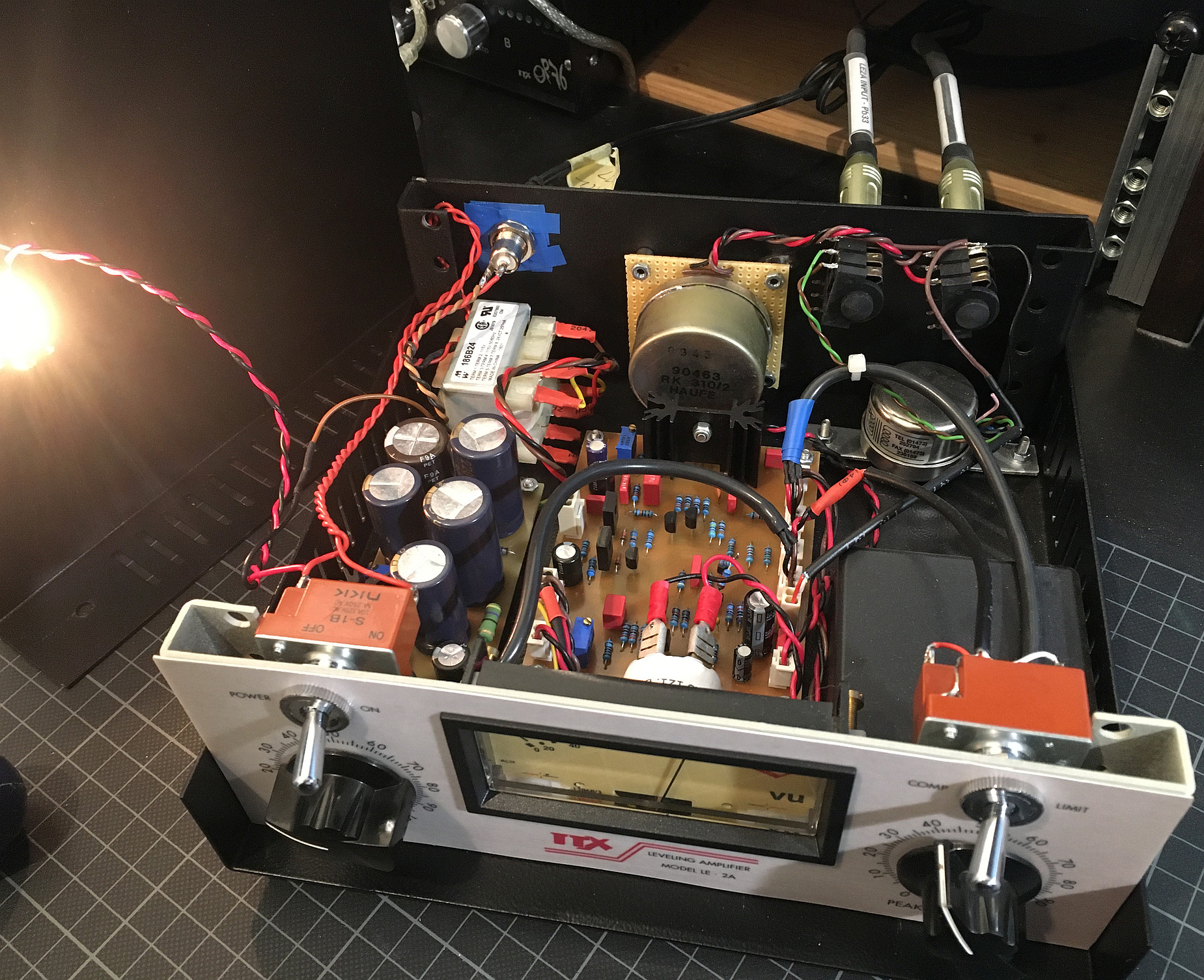
Thanks for asking. I did a lot of personal projects and the LE2A* is one of them. It's my own version of a transistorized LA2A with home brew T4 cell that sounds amazing on bass guitar and vocals. No tubes were harmed during development but as it's on self-etched PCB's, it's not DIY friendly at all... ;)

le2a_lid.jpg

* LE is not a typo, just a reference to my hometown

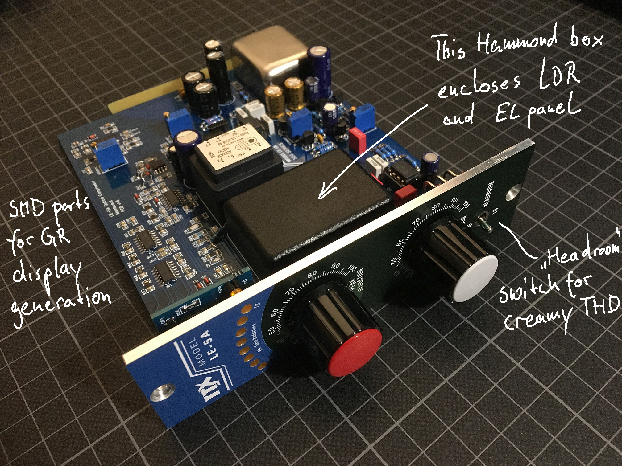
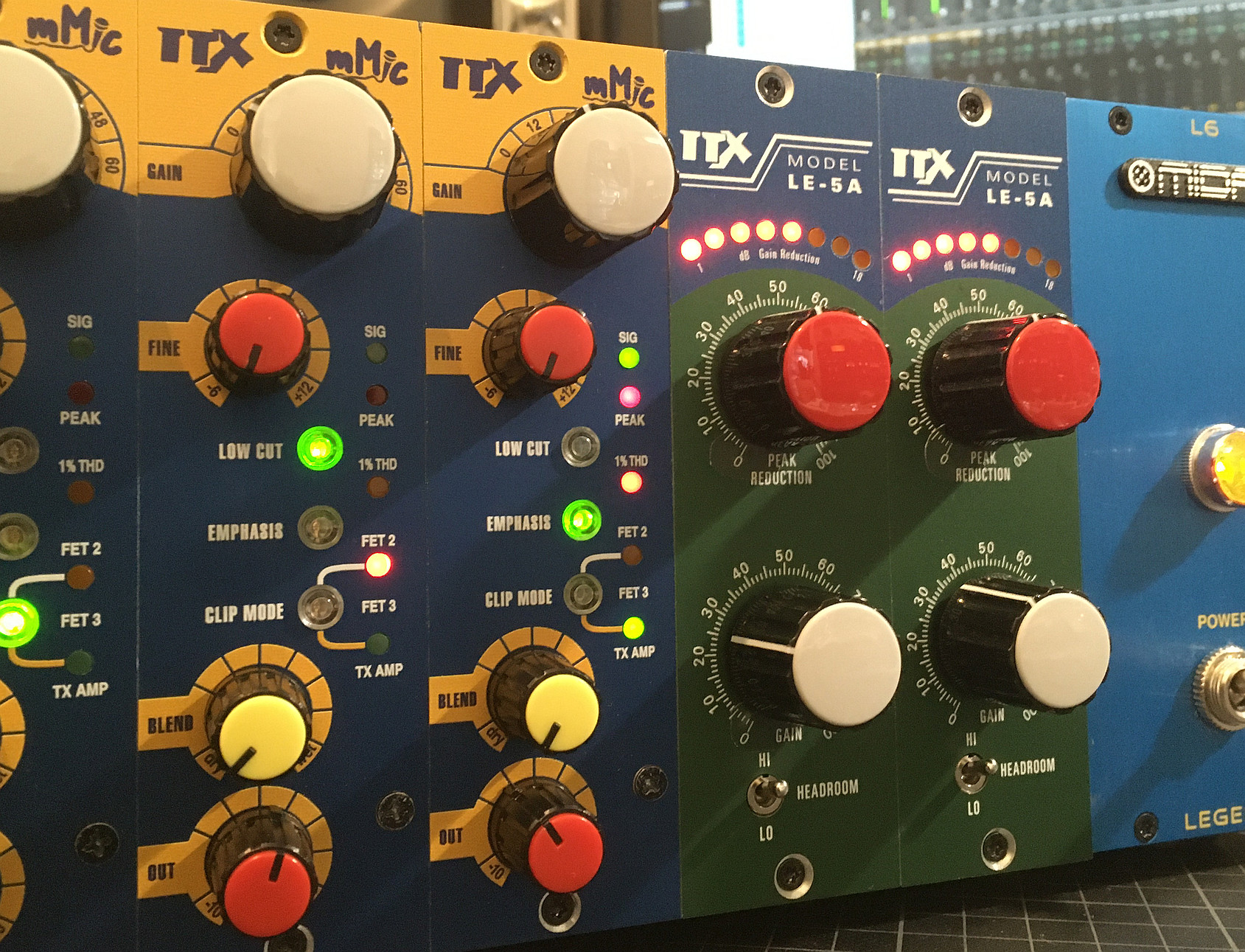
However, I recently had another attempt at an optical compressor for 500 series that uses off-the-shelf parts (including the LDRs which are still available in some places). Sounds great as well :)

le5a_exp.jpg
le5a_working.jpg


Mind you, it's not a copy of anything existing. I was just putting together a couple of ideas which (after two revisions) turned out great. The version you're seeing is still not the final one.

If there's some interest, I could try and turn this into a DIY project by offering the PCBs and putting together a guide. Anyone interested?
 
Last edited:
TTx OP76 - new batch of PCB's available.

Board revision v2.3 fixes the wrong component footprint for the XLR input connector. The guide has been updated accordingly. For those with earlier board versions, the section with a possible fix remains in there for reference.

I still have ONE (1) last board of former rev. v2.2 left. If you don't mind the erroneous footprint you may order that one for the reduced price of 20 Euros + shipping. = GONE.

See the first post in this thread on how to contact me if you're interested :)
 
Last edited:
I don't have a J109 handy and Mouser is out until September. Could I sub in another JFET switch like J112 or J113? I've been looking for a good substitute, but I'm not sure which specs are most important for Q4 to work properly: Rds(on), Vgs(off), Idss?
 
Could I sub in another JFET switch like J112 or J113?

Yes, they should work.

Just make sure to check the DC offset at the output of U3 (Pin 7) and rotate C20 accordingly (see the Errata section in the guide for details). If the DC offset turns out to be more than 3 to 4 volts in either direction you can try and compensate by changing R15 to a different value - higher resistance means more positive DC offset and vice versa. It doesn't have to be zero - within +/- 3-4 Volts is fine.
Right on the money! With the J112, Pin 7 is around -2.42V, so I flipped C20. It also drops the J112 Source voltage to ~2V, is it worth re-biasing that stage to get closer to 5V SPICE says it would be with the J109?

On the breadboard, I'm running this unbalanced at the moment and am having trouble getting the Input control to be useful along more than a narrow band of travel (towards the top end). I'm wondering if the input signal is too high/low for the FET to deal with (I've run into this with FET compressors before).

Any idea what kind of signal level the line receiver would be kicking out? On my sim I've been targeting ~3.5Vp-p, thinking it was +4dBu, but that was enough to clip U3.2 with the input cranked (assymetrically, due to the voltage offset I guess?).

I'm also using 2N5457s set up as low-leakage diodes at the moment as I don't have any FDH333, could that be messing with the FET response?
 
... is it worth re-biasing that stage to get closer to 5V SPICE says it would be with the J109?

Not needed.

I'm also using 2N5457s set up as low-leakage diodes at the moment as I don't have any FDH333, could that be messing with the FET response?

Replace the FDH333 with 1N914 or 1N4148. I don't see how a JFET as the 2N5457 can substitute a diode. Maybe this also helps with your input control not driving the signal into compression (at least this is how I understood your question, please correct me if I'm wrong).
 
Not needed.


Replace the FDH333 with 1N914 or 1N4148. I don't see how a JFET as the 2N5457 can substitute a diode. Maybe this also helps with your input control not driving the signal into compression (at least this is how I understood your question, please correct me if I'm wrong).
I'll give it a shot with the 1N4148. You can hook up a JFET as a very low-leakage diode: Diode & Source as Cathode, Gate as Anode. I've come across it on a few threads here, but it's probably better to try it later on.

Previously you said "signal level has to be extremely low (<<100mV) at the gain reduction FET for it to remain in its linear region", is that closer to 1-10mV or 10-100mV (on the JFET Drain)?

I think the JFET is seeing 60-180mV+ on my breadboard at the moment, so I am wondering how much I need to attenuate it.
 
Back
Top