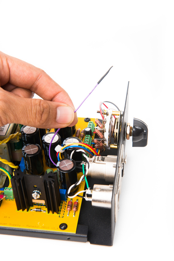
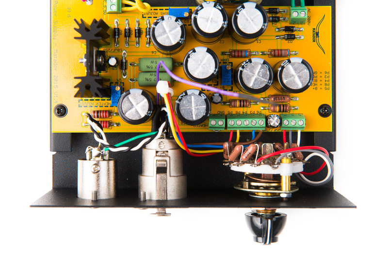
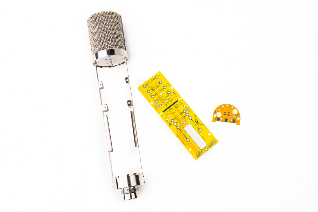
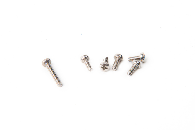
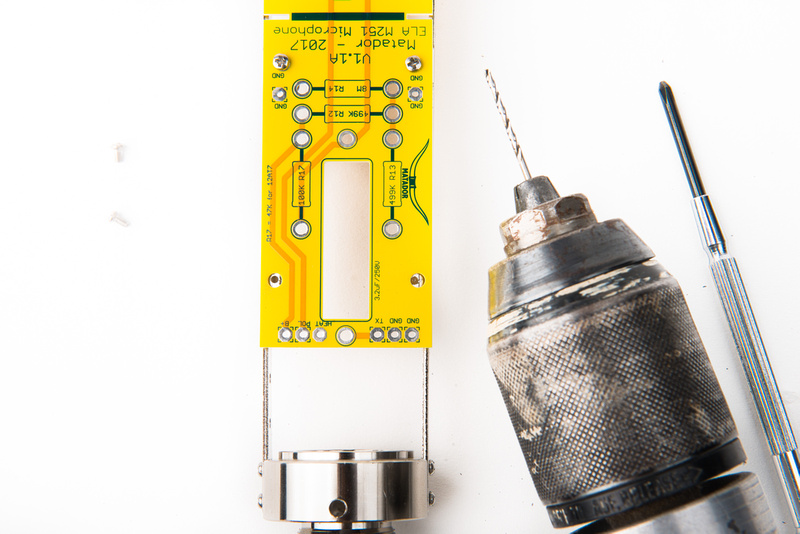
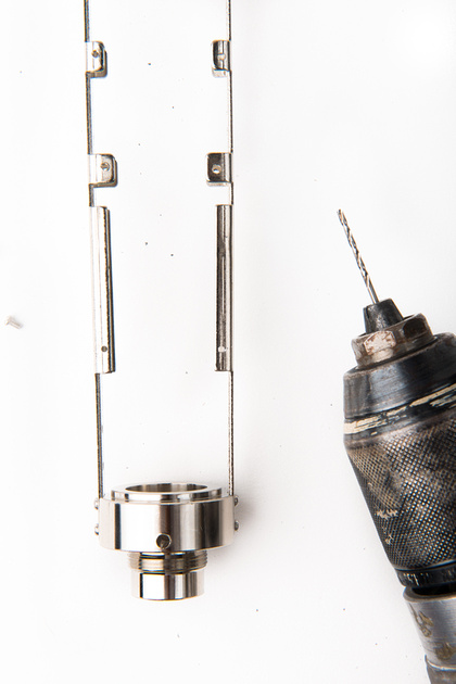
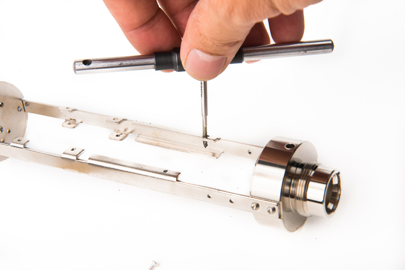
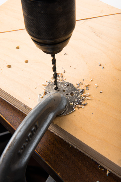
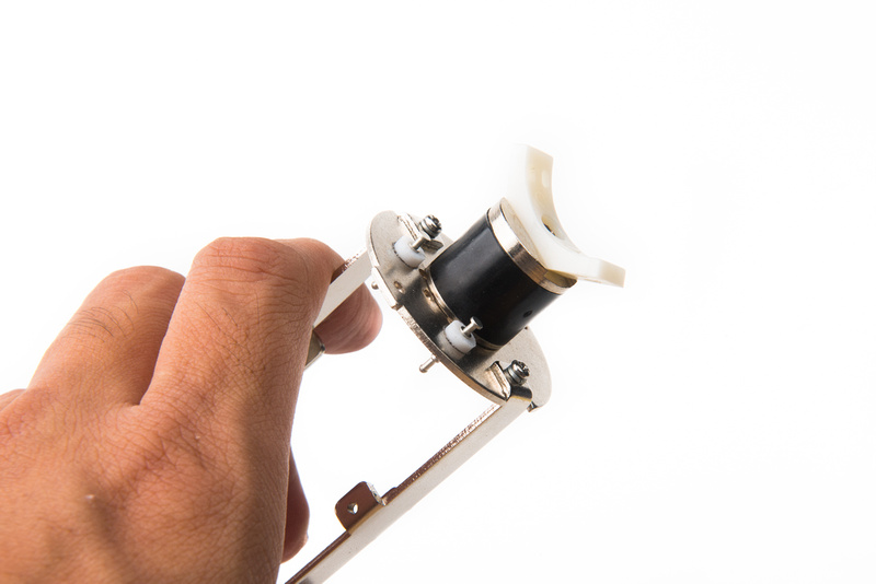
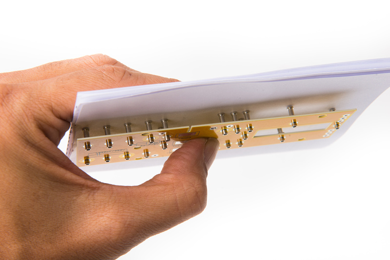
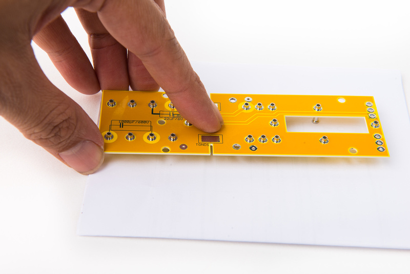
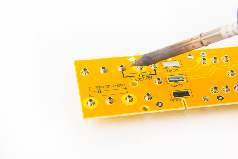
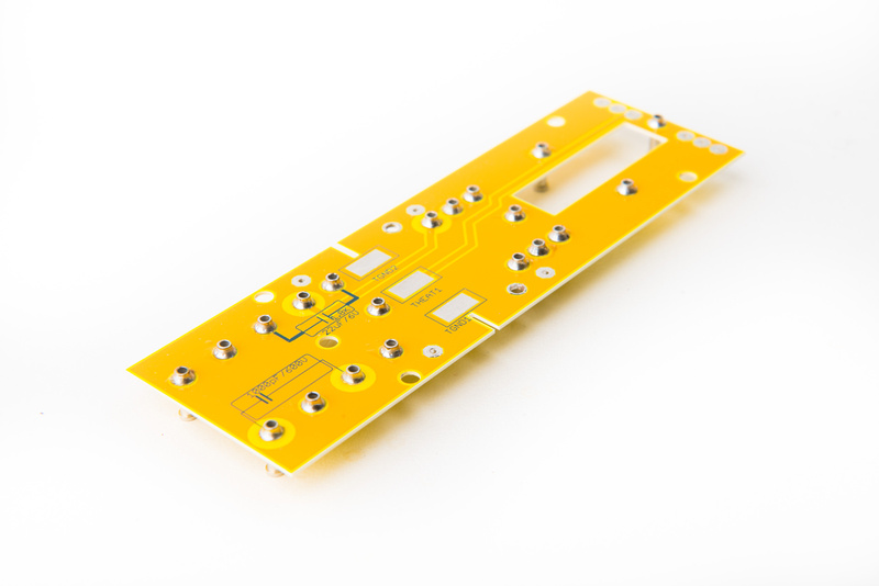
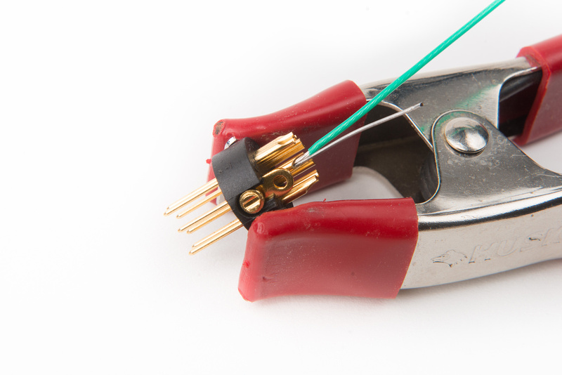
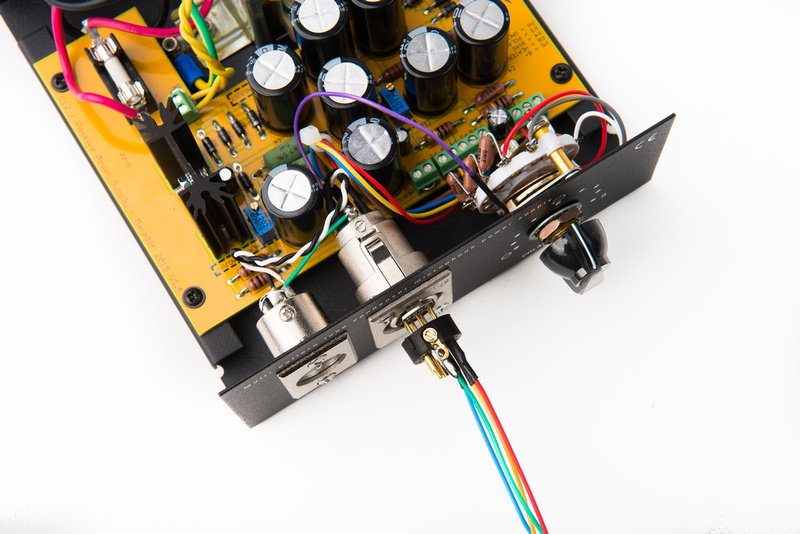
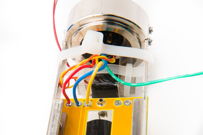
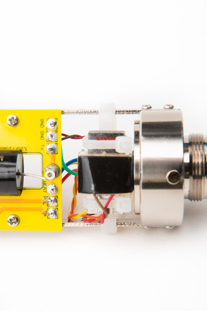
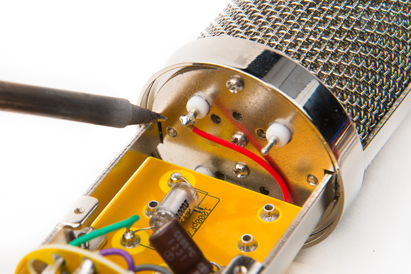
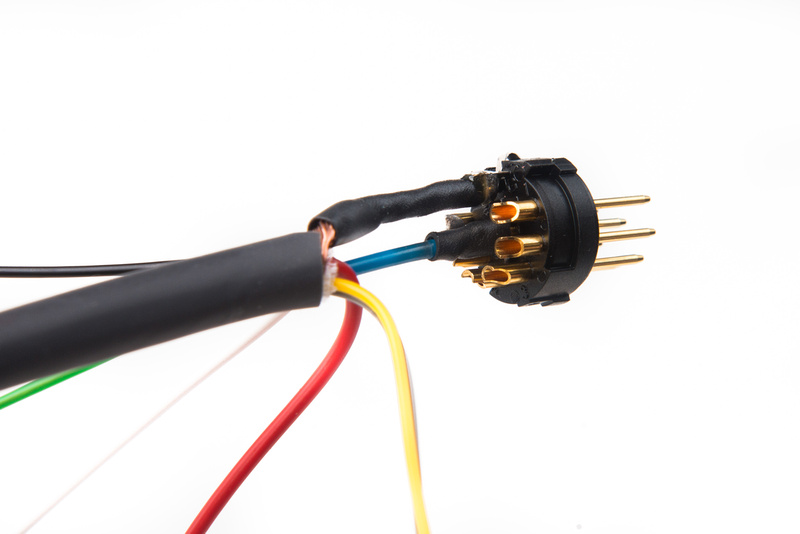
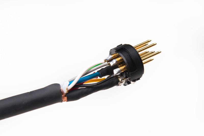
Next, we will prepare the 7 pin XLR insert that goes into the microphone body. Note, the set screw securing this insert works in reverse! To secure it to the microphone body, back the screw out (counter-clockwise) until it pushes outward onto the microphone body. To remove the screw, drive it in (clockwise) to the stop. The insert should wiggle out.
There are many ways to ground a microphone/power supply setup and there is debate about which was is the most proper. I am choosing to connect the ground lead to the microphone chassis at the XLR connector, so the first step is to set the ground wire and run a jumper from that solder lug to the chassis grounding lug on the XLR insert.
Next, we will populate the XLR insert with short wire leads corresponding to the pinouts and wire colors that we selected when building the power supply. In my specific build, I will be using the following:
Pin 1 = B+
Pin 2 = heater
Pin 3 = pattern
Pin 4 = unused (bias in my C12 builds)
Pin 7 = ground
We will leave pins 5 and 6 empty for now as the transformer will connect directly to those.
I like to visually confirm that all of the wires are aligned properly to the PSU wires just to make sure things will not get crossed up during assembly.
With everything confirmed, apply some shrink wrap to the solder lugs.
For this build, we will be using the Cinemag CM-13114 transformer.
The wiring diagram for this transformer as provided by Cinemag shows how to get things set up.
But, mistakes in production have been known to happen, so let's confirm with with a multimeter before putting the transformer into the microphone.
One side of the transformer will have higher resistance than the other. The higher side will go to the PCB, the side with the lower resistance will got to the XLR insert.
Brown and Red measure 1.4K, which is the high side. These two wires will connect to the PCB.
Orange and Yellow measure 29.5R, which is the low side. These two wires will connect to our XLR insert.
Take the orange and yellow wires and thread them through the threaded base piece of the microphone body.
I am designating orange as "audio +" and yellow as "audio -" so we will solder them:
Pin 5 = orange transformer wire
Pin 6 = yellow transformer wire
Push the XLR insert into position and secure the set screw by turning it in reverse (counter clockwise).
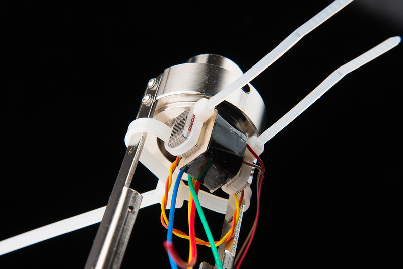
A bell housing is available for the HT-11a microphone body for mounting the transformer, and that can certainly be used, but I prefer to use zip ties and keep everything visible.
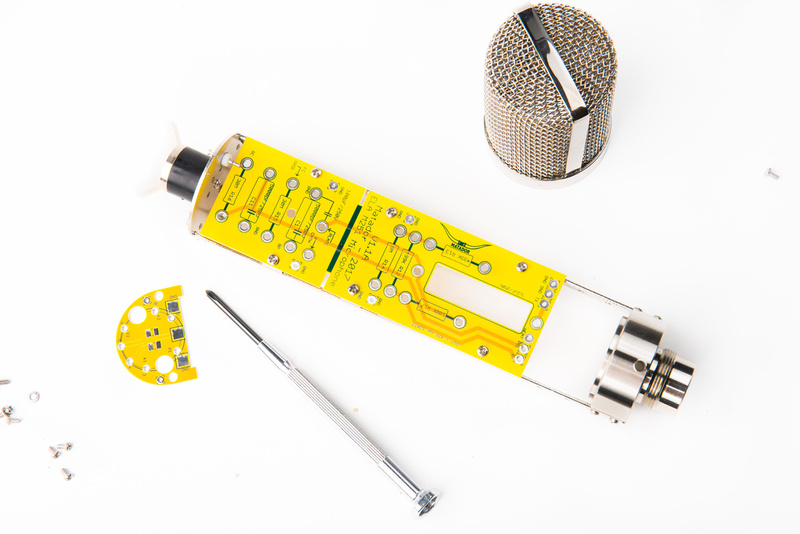
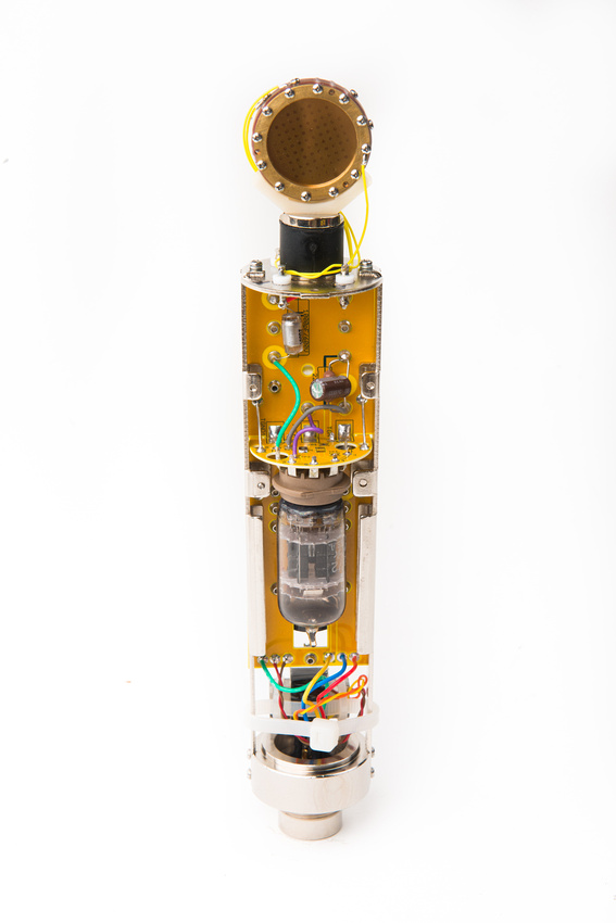
We can now attach the fully populated PCB assembly to the microphone body.
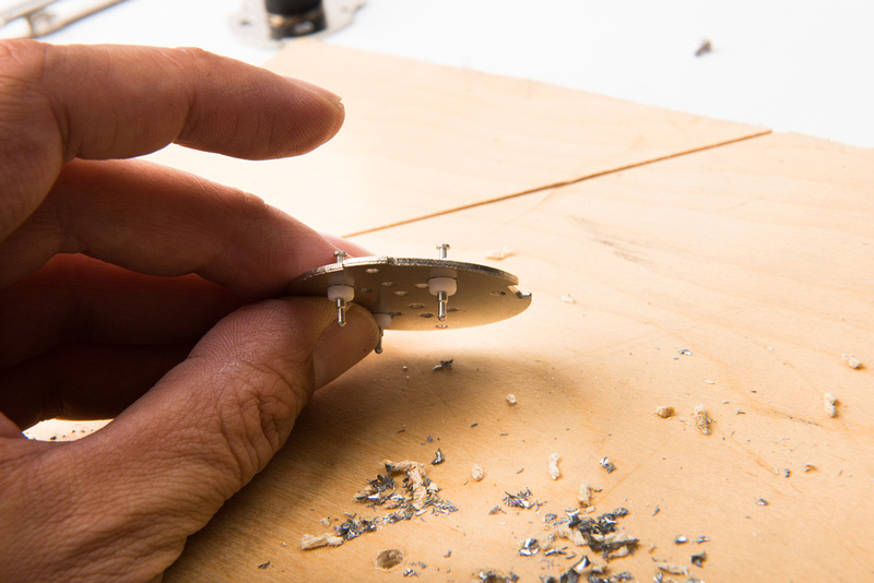
To avoid interference, one of the capsule turrets that I previously installed needs to get cut short.
After cutting, I solder in a wire lead to the turret. Again, these turrets are completely optional and not included in the kit. I am setting it this way to facilitate easier capsule swapping for testing on this microphone platform.
Next, locate the M2 screws and secure the PCB to the frame rails.
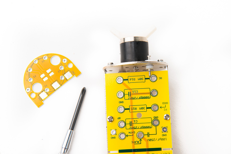
Prepare the wire leads from the XLR insert and route them to the correct solder points on the PCB. It never hurts to double check things here to make sure everything is wired the same as in the power supply.
For my wiring scheme:
B+ = Red wire
POL = Blue wire
HEAT = Yellow wire
GND = Green wire
next, locate the brown and red wires from the Cinemag CM-13114 transformer or the two wires with higher resistance from the transformer that you are using in your build. For my wiring scheme,
TX = Brown wire
GND = Red wire
And here is how it looks with the XLR insert all wired up.
Next, we can make the capsule connections at the top of the microphone. I am designating this turret for rear capsule, and the black wire should route to the turret labelled "RC".
I select this turret for front capsule and route the red wire to the turret labelled "FC"
The last turret is for backplate, and I route the corresponding blue wire to the turret labelled "BP"
With everything wired up, we can clean the flux off of the PCB with some 90% isopropyl alcohol and Q tips. Again, be careful around the capacitors.
For this build, I will be using an Eric Heiserman HK12 capsule which is a "proper" chambered capsule. Please note, the Heiserman capsule has isolated backplates that we will need to "tie together" on this build because we retain the polarizing scheme from the C12 microphone. For this build, I will simply run both backplate leads to the same teflon capsule turret.
The Heiserman HK12 capsule uses a 45 degree 34mm capsule mount (wide type). I prepare the saddle by clipping off the retaining tabs on the bottom as those are not needed for the rubber base piece on the Alctron mount that comes with the HT-11A microphone body.
Swap in the 34mm wide capsule mount.
And install the microphone to the saddle.
After selecting the screw tabs that I will use for the capsule leads, I install all four lead wires and solder the capsule to the teflon turrets on the microphone body. A ziplock bag protects the capsule from solder splatter.
And here, the capsule is installed.
We can now prepare the microphone cable. I am using Gotham GAC 7 cable which has two thicker 20AWG wires that should be used for the heater and ground connections for this microphone build.
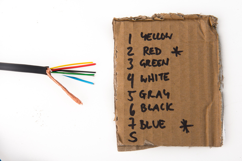
In order to keep everything straight in my head, I make a little pinout chart to keep me on track when I assemble the cable ends.
For my build, I will be using:
Pin 1 = Yellow
Pin 2 = Red (20 AWG wire)
Pin 3= Green
Pin 4 = White
Pin 5 = Gray
Pin 6 = Black
Pin 7 = Blue (20 AWG wire)
Obviously, this can be changed to suit your preference. Before soldering, be sure to slide the retainer piece over the cable! Forgetting this step can lead to a lot of headaches.
There are many ways to set up the grounding scheme on the power supply, microphone, and cable and some people choose to tie the ground and the shield together. For this build, I am opting to keep the ground wire (pin 7) and the shield separated so I use some shrink wrap and solder the shield to the appropriate tab on the connector. The blue ground wire goes to pin 7. These are the hardest connections to make so I do them first.
Referencing the diagram that I made, I make the rest of the wire connections.
The male end of the cable is similar. Again, the shield and ground connections are the most difficult so I execute these first. Make sure you remember to slide the retainer shell over the cable first before soldering the 2nd side of the cable!
Again, I reference my diagram and make the rest of the connections as cleanly as possible.
With the cable completed, I insert an expendable but known working tube for initial testing. I have an Electro Harmonix 6072A for this job.
And here is the moment of truth. Triple check everything before powering up the microphone for the first time!
No smoke! we are sitting at 117.3V for the B+ which is fine.
And the heater is sitting at 6.28V which is also great.
With no outer casing on the microphone it will be a rumbly, hummy, noisy mess. . . don't worry about that for now. We are simply function testing.
Power down the microphone and remember to wait a sufficient amount of time for the power supply capacitors to fully drain. This may take a few minutes. Once fully powered down, unplug the microphone and install the outer tube. Now, we should have a quiet, clean signal. Check for patterning to make sure that is working properly.
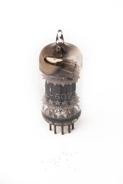
With everything confirmed working, it's time to swap in the final tube. I will be using a 1953 GE6072A 5 star tube supplied by Christian Whitmore. These are selected for noise and microphonics and burned in so they should function flawlessly from the start without drama.
Because this microphone only uses one half of the tube, I save a little bit of money by obtaining a tube that tests quiet on only one side as indicated on the box.
Carefully install the tube!
For the final setup we will want to adjust the heater voltage measured at the microphone as there will be loss over the length of the cable. We start at 6.22V which is fine, but why not get it exact.
A few turns on the trim pot in the PSU, and we dial in 6.3V
The B+ is also adjusted to 119.9V. Because this part of the PSU is passive, the voltage will wander based on the wall power in your specific location. I monitor this for a few minutes and set the PSU to average spot. This voltage should not exceed 120V.
And the microphone is completed. Humans Win!


