efinque
Well-known member
- Joined
- Jan 3, 2018
- Messages
- 393
Sup GDIY,
I thought I'd start a new thread for this project to keep the previous one on track.
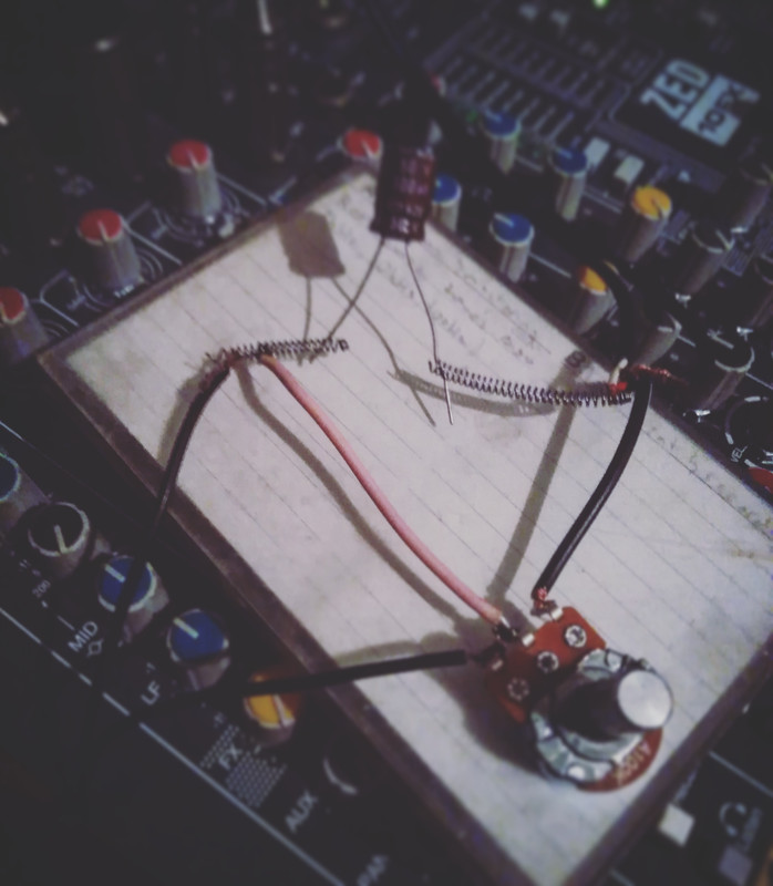
Anyway, one evening I got bored and coiled a simple transformer as well as rolled a few capacitors. Then I took apart a small mixer build I had made from leftover components and put together a crossover.
Here's some testing I was making earlier (it was originally for a synth)
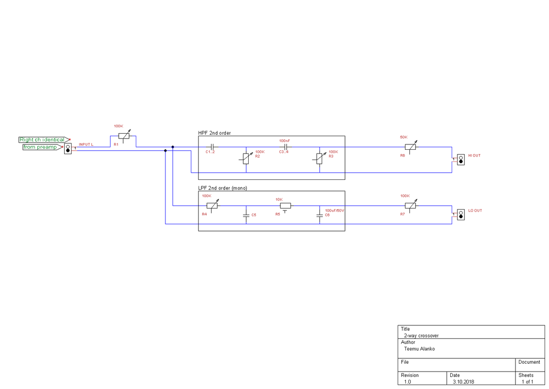
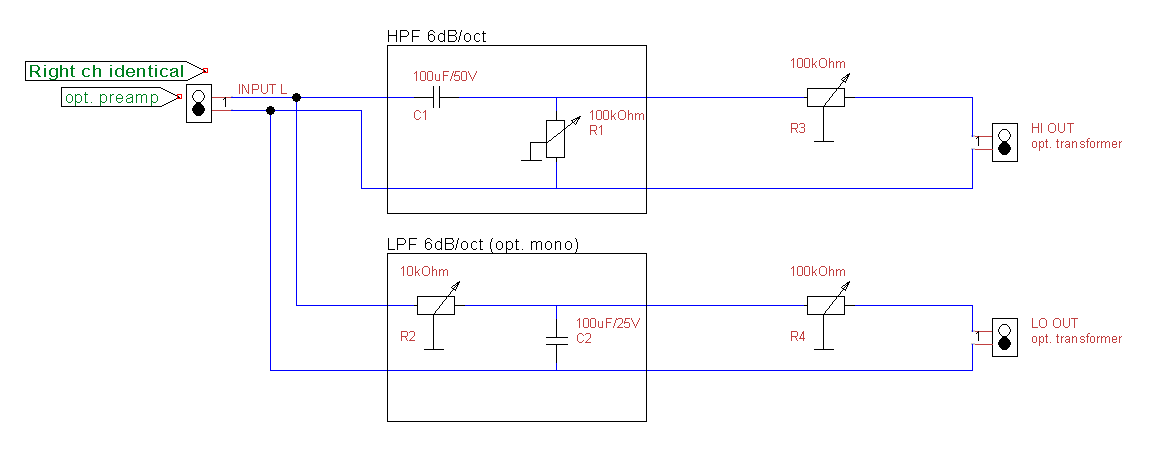
Here's the initial schematic for the crossover (ignore the component values, the prototype uses DIY caps)
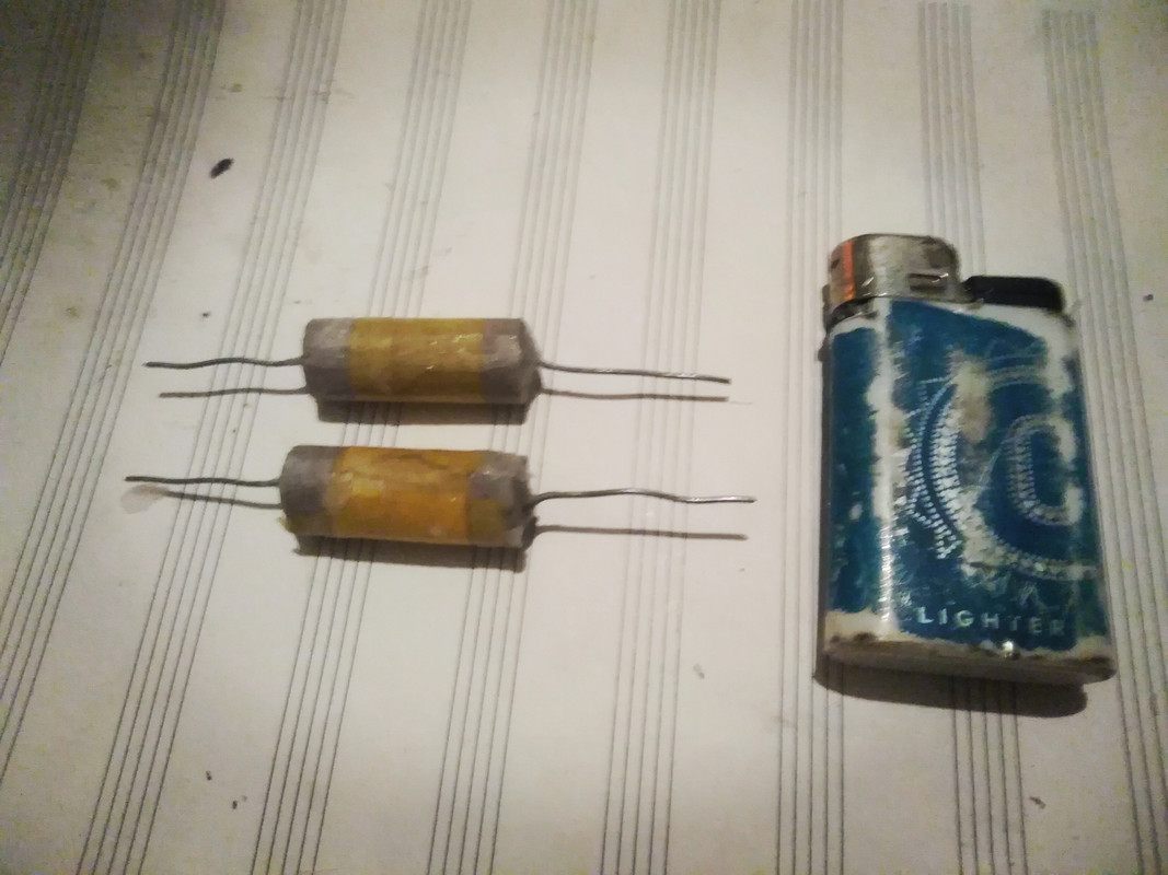
Some components (I have some off-the-shelf caps too but I'm afraid they're either too small or too big.. the protype uses a preamp)
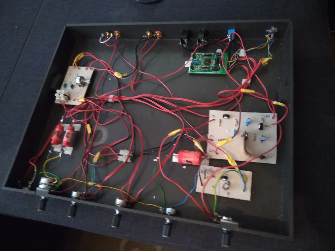
Here's the case with internals
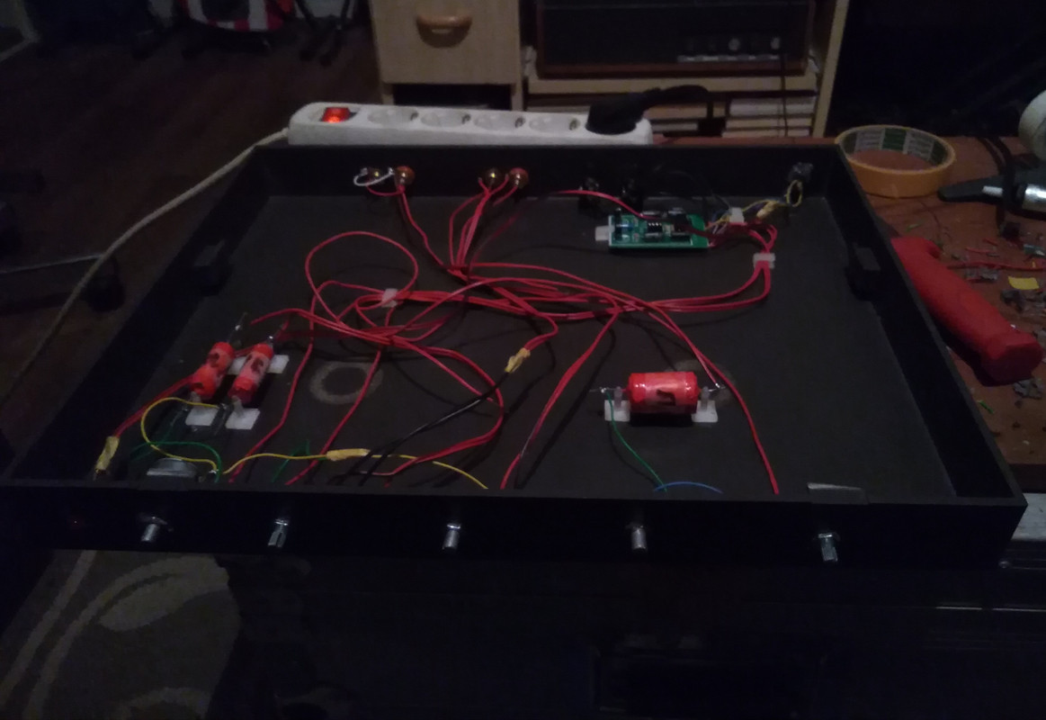
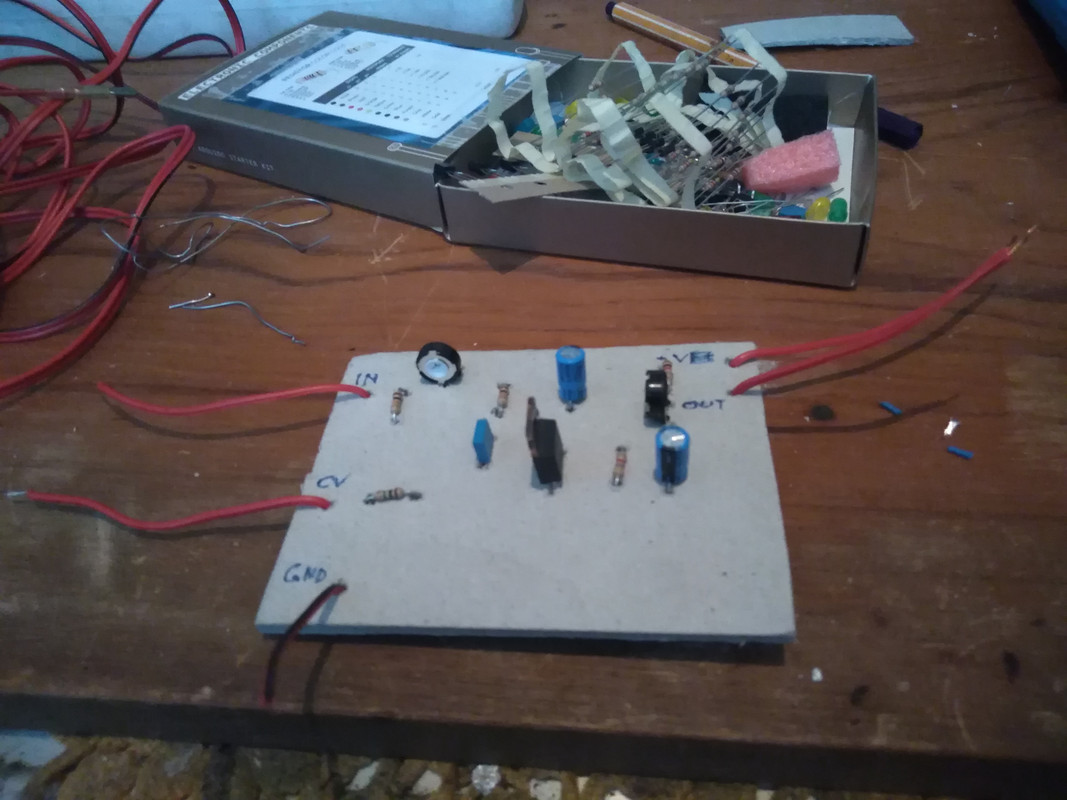
And a close-up of one of the modules.. (edit : I might make a proper PCB if I get around to it.. cardboard isn't quite professional yet very retro)
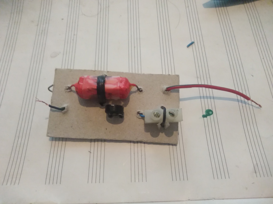
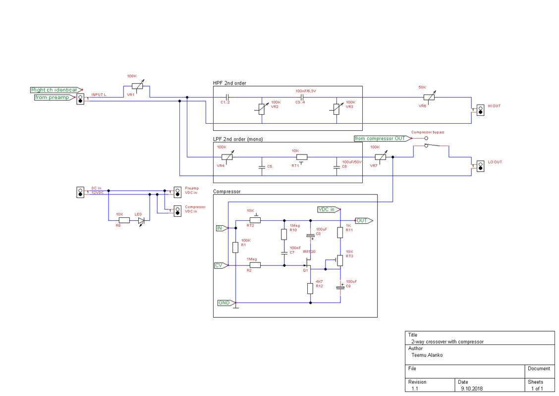
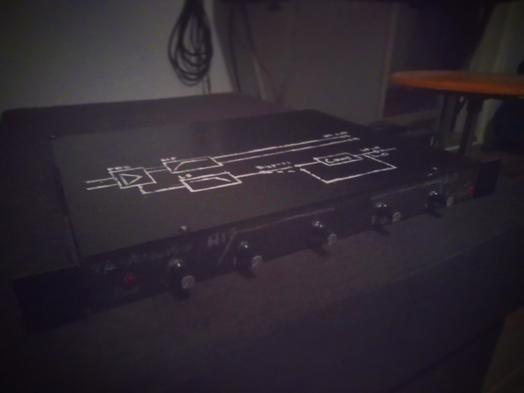
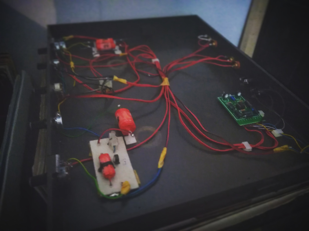
As of now it looks something like this :
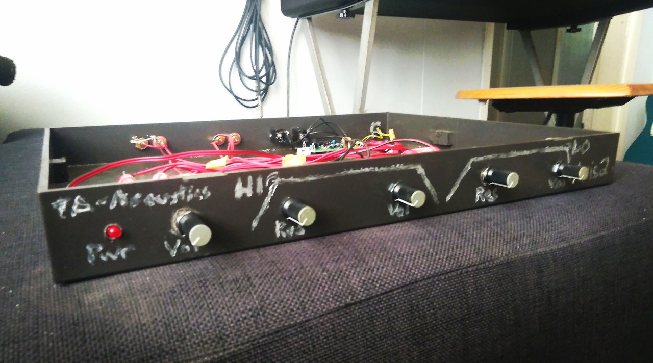
Here's a front shot (I accidentally painted the freq curves the wrong way around) :
Now, I have a few questions... I don't have a cap tester, or amps to do passive tests with, as well as having a go at calculators for cap values which brings into mind a few questions... is it generally speaking better to use inductors? Or multiple smaller caps to get close to the exact values? The high band is a stereo 1st order and the low is a mono cascaded 2nd order filter (I have some modules to up the HPF 2nd order or put them in series with tweeters)
The idea isn't to tweak the xover every once in a while to match the input signal hot enough to keep it running.. I may try with some other caps (I've been looking at Amp Ohm, Audyn and Nichicon) as it's very quiet atm.
Thanks in advance,
-ef
EDIT : one idea was to make the filter network active..
EDIT 2 : another question is whether it's a good idea to keep the 2nd and higher order filter resistor values the same with a single pot?
EDIT 3 : almost everything has been done so far by ear and intuition.. although I might make a calculation or two to make sure I'm on the right track every once in a while. Some of the modules have a nice thump to them.. others sound very gritty. My guess is that the caps last a year or so, because they're essentially tin foil, paper/cardboard, felt/fabric, stearine/parafin and oil. I made a few from aluminium and copper sulphate, sealed with hot glue.
EDIT 4 : I'll revise the schematic once I get around to it..
I thought I'd start a new thread for this project to keep the previous one on track.
Anyway, one evening I got bored and coiled a simple transformer as well as rolled a few capacitors. Then I took apart a small mixer build I had made from leftover components and put together a crossover.
Here's some testing I was making earlier (it was originally for a synth)

Here's the initial schematic for the crossover (ignore the component values, the prototype uses DIY caps)

Some components (I have some off-the-shelf caps too but I'm afraid they're either too small or too big.. the protype uses a preamp)

Here's the case with internals

And a close-up of one of the modules.. (edit : I might make a proper PCB if I get around to it.. cardboard isn't quite professional yet very retro)

As of now it looks something like this :

Here's a front shot (I accidentally painted the freq curves the wrong way around) :

Now, I have a few questions... I don't have a cap tester, or amps to do passive tests with, as well as having a go at calculators for cap values which brings into mind a few questions... is it generally speaking better to use inductors? Or multiple smaller caps to get close to the exact values? The high band is a stereo 1st order and the low is a mono cascaded 2nd order filter (I have some modules to up the HPF 2nd order or put them in series with tweeters)
The idea isn't to tweak the xover every once in a while to match the input signal hot enough to keep it running.. I may try with some other caps (I've been looking at Amp Ohm, Audyn and Nichicon) as it's very quiet atm.
Thanks in advance,
-ef
EDIT : one idea was to make the filter network active..
EDIT 2 : another question is whether it's a good idea to keep the 2nd and higher order filter resistor values the same with a single pot?
EDIT 3 : almost everything has been done so far by ear and intuition.. although I might make a calculation or two to make sure I'm on the right track every once in a while. Some of the modules have a nice thump to them.. others sound very gritty. My guess is that the caps last a year or so, because they're essentially tin foil, paper/cardboard, felt/fabric, stearine/parafin and oil. I made a few from aluminium and copper sulphate, sealed with hot glue.
EDIT 4 : I'll revise the schematic once I get around to it..


