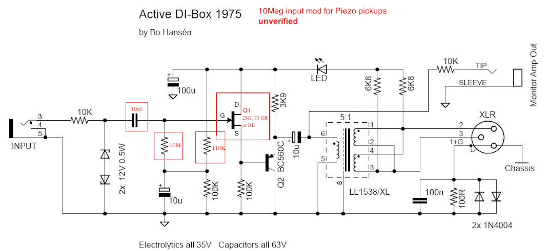
When I looked at the schematic(I like the low parts count well thought out circuit) I wonder why I have not seen one with a bootstrapped buffer stage for a little more input impedance?
I like it uses BJTs. I avoid JFETs when I can.
Remove the filter cap at the bias network and install a cap from the 2nd transistors emitter to the input 470ks and 1meg node. I would then reduce the 470 bias resister values.
There is nothing wrong with the stock circuit this idea is if you want more input impedance if the device driving the DI works better into a higher impedance. You need to be careful with the cap value picked.


![Soldering Iron Kit, 120W LED Digital Advanced Solder Iron Soldering Gun kit, 110V Welding Tools, Smart Temperature Control [356℉-932℉], Extra 5pcs Tips, Auto Sleep, Temp Calibration, Orange](https://m.media-amazon.com/images/I/51sFKu9SdeL._SL500_.jpg)