Discrete Opamp with differential output?

GroupDIY Audio Forum

Help Support GroupDIY Audio Forum:

This site may earn a commission from merchant affiliate links, including eBay, Amazon, and others.

Matador

Well-known member
Joined
Feb 25, 2011
Messages
3,067
Location
Bay Area, California
Does anyone have any resources for designing an op-amp with fully differential outputs?

There are plenty of examples of single-ended output op-amps, but I'm think something more along the lines of the AD8138:

ad8138-cdl.png


I'm thinking: if you took a standard LTP differential pair like this:

Long-tailed+pair+with+emitter+current+source+and+diff.+output.png


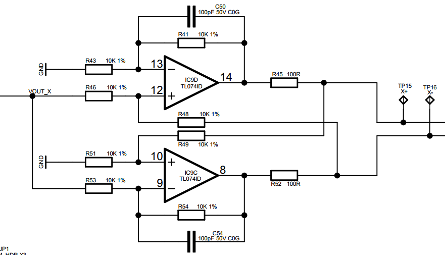
Neglecting current drive (e.g. output) capabilities, if the two outputs were buffered, they could be returned to each of the inverting and non-inverting inputs with a standard differential amplifier topology, and this simple circuit should be able to provide two buffered differential outputs., right?

I haven't seen any published plans for a differential output discrete amplifier, so any leads are welcome.
 
I’ve seen LTP as going into op-amps but never as an output amp I think possibly because it’s a transcuctance amplifier which amplifies with respect to current?

Cool question  8)
 
What will it be driving? Even ignoring current drive,  taking the outputs from the collectors will be higher output impedance than you would typically want from an opamp.

The attachment might be useful.  Outputs are collectors that go through unity gain buffers.
 

Attachments

  • sloa054e.pdf
    867.6 KB · Views: 34
DOAs generally have enough components squeezed in them to desire making them even more complicated. Further IMO there is merit to first single ending a differential input signal before making it differential again for output, scraping out common mode noise, etc. I never ASSume following stages are as good or better than the stages I am designing, so try to do the heavy lifting, when and where I can.

JR

PS: I have seen at least one IC design, from back when they published innards of solid state ICs with dual symmetrical differential inputs (sorry don't remember exactly which one). Some of these published innards of ICs include devices not available as discrete components (and/or schematic may symbolic not literal).
 
mjrippe said:
Do a search for Valley People Trans-amp.  I know there were some DIY attempts here.
The transamp is based on what we now call the "cohen" topology. It is designed for low noise at high gain and IIRC used TL072 opamps inside, so not very robust drive capability,,, Intended to feed a differential amp.

Have you looked at THAT chips... They make some balanced line drivers that might work ?

JR
 
JohnRoberts said:
The transamp is based on what we now call the "cohen" topology. It is designed for low noise at high gain and IIRC used TL072 opamps inside, so not very robust drive capability,,, Intended to feed a differential amp.

You are correct, John.  I found this schematic on my computer.  Although it is not fully discrete, it does say 553x may be used for better drive.
 

Attachments

  • DIY TransAmp?.jpg
    DIY TransAmp?.jpg
    29.5 KB · Views: 67
JohnRoberts said:
Have you looked at THAT chips... They make some balanced line drivers that might work ?
I have, but I haven't found a biasing scheme that allows them to work with a single supply rail.

I had originally considered this:

WZFKU.png


But that is sensitive to careful selection of the feedback resistances.  You can get laser trimmed differential opamps, but they are expensive and incredibly noisy (like >80 nV/sqrt(Hz)):

7750.Slide_2D00_0001.JPG


Since this circuit I'm working on is designed to drive a regular XLR into a 10K input impedance, maybe it's just better to xmit single ended and just implement impedance balanced outputs?
 
mjrippe said:
You are correct, John.  I found this schematic on my computer.  Although it is not fully discrete, it does say 553x may be used for better drive.

there are two errors on this schematic, both the two TL072's have the plus and minus inverted between them.
BTW  the minus input is the pin 2 and not the pin 3 as indicated there, moreover, the plus is the pin 3 and not the pin 2 as indicated. On the second opamp the minus should be the pin 6 and not the 5, the plus should be the pin 5.

Pier Paolo 
 
ppa said:
there are two errors on this schematic, both the two TL072's have the plus and minus inverted between them.
BTW  the minus input is the pin 2 and not the pin 3 as indicated there, moreover, the plus is the pin 3 and not the pin 2 as indicated. On the second opamp the minus should be the pin 6 and not the 5, the plus should be the pin 5.

Pier Paolo
The schematic has mislabeled the op amp symbols but used correct pin numbers for +/- inputs.

That said the schematic looks different from the original transamp design. IIRC the transamp used a slightly different topology with each half TL072 providing negative feedback wrapped directly around each pair of input transistors.

The op amps in series to provide two polarities of feedback ultimately tied back to the input transistors is a variant I saw elsewhere later but not inside the original transamp AFAIK. That op amps in series design used an RC across the first op amp +/- inputs for stability to compensate for lag (delay) sending negative feedback through the second op amp. The same thing that schematic is doing with the 10pF caps. So it may be a working design, but I am not sure it is Paul's. Many people used this "Cohen" topology (me included since the late 70s. )

I don't think Paul Buff (RIP) ever published an official internal schematic for transamp but recall seeing one Valley Audio preamp schematic around the internets that looked similar.

JR
 

Latest posts

Back
Top