RFZ V241 Mods

GroupDIY Audio Forum

Help Support GroupDIY Audio Forum:

This site may earn a commission from merchant affiliate links, including eBay, Amazon, and others.

Murdock

Well-known member
Joined
Jan 28, 2015
Messages
858
Location
Germany
Hey,
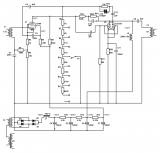
I would like to ask for some ideas concerning modding the V241 circuit.
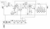
Thought about using the V41 input and gain switch topology.
But I have no idea where to implement the gain switch. In between the two stages or like the V241 after the output cap?


Also, where would be a good spot to implement a switchable low cut filter of 80Hz and 120Hz?
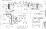
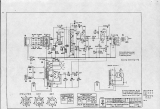
I looked at different designs, like Therapy pre and G9 where there are just capacitors or the V76 with LC filter...
But fail to understand exactly how they work and are best implemented, thinking about impedance and stuff.


https://s17.directupload.net/images/190311/5cpigoda.png
 
OK, tried to draw a version.
As you probably can see, I don't really have a clue what I'm doing  ::)
Would it even work like that?

 
Nobody?  :-\
Would try it on the breadboard but want to make sure that at least nothing will break....
 
V241 *has* a gain-switch.

What are you doing that smart German engineers didn't anticipate?

 
I read that it's always better to go directly to grid without anything inbetween... Most of the "high class" tube preamps do it that way.
I would like to try both topologies but want to make sure I don't blow anything up with the modification  ::)
 
You have in the V241 a very carefully worked out feedback network , each gain setting  has its own compensation components , every component relates some way to the others around it and the transformers , and all combine to give the performance the designer set out to get , I'd go with Pauls advice , dont tinker with it if its not broken .

I worked on a few East German EF12k preamps , appart from one or two solder joints needing attention ,they powered right up and worked great after a few hours  settling time . The right source and mic combination with the V241 and you should already be getting a great sound .

Why not try out your other circuit ideas on a newly constructed chassis.


Thanks for your replies!
I don't have an original. Sorry for the missunderstanding!
I would like to build one of these but maybe with some modifications.

As you say Tubetec, it is "a very carefully worked out feedback network and every component relates some way to the others around it and the transformers".
And as I don't have the original transformers it would probably be "out of spec" anyway, wouldn' it?
I wanted to try both topologies, the original and the V41 type direct to grid.
Like I said, just wanted to be sure I don't blow anything up.
Is there anything inherently wrong with my schematic?
 
It might work , probably not as you expect it to without changeing out components
I bet theres tons of old radio and broadcast equipment in Belgium ,probably a mix of Dutch German and French as well as some locally manufactured stuff . You might be able to find a phonographic society or group dedicated to old broadcast gear. Flea markets are also probably worth a look and enquire with the traders there.
The kinds of choke and transformer used in these units are difficult or impossible to reproduce nowadays ,Sowter does some replacement bits for Tele/tab modules which are somewhat similar to the RFZ. Maybe check for local transformer winders with some history in audio if they still exist .
 
> I read that it's always better to go directly to grid without anything inbetween...

The V241 signal *does* go "directly to grid..." And in all switch positions.

While preamps are hard to blow-up, you won't get a Blanket Blessing from anybody with experience letting smoke out unexpectedly. Things do go wrong. You need a window fan.
 
You can’t just cut and paste circuit sections that are designed for different tubes.  You may just want to do a Lorenz using Paul’s tips or a Redd.  Good try though
 
Yeah, thought as much... I'll just build it with the original topology.
Thanks for your answers!

How about implementing a low cut filter in the V241 circuit? Preferably switchable between 80Hz and 120HZ.
Would a switchable 53k and 84k ohm resistor in parallel to "W9" (2M Ohm) work? So it forms a simple RC high pass with "C5" (25nF)?

 
There’s 2 problems w that. Main problem is bringing the grid of v2 too close to ground and being inside the NFB loop. Best to  use  a HP before the input trannie or between input XFMR and V1.
 
Hmm, I assume with an LC Filter like V76 also wouldn't work for the same reasons?
How would you implement it between input XFMR and V1? Also with a simple RC HP?
 
Choke load with parallel fed transformer, done right its the best you can get always has been , doing it right even back then took German fastidiousness ,in the modern day your probably going to end up having to roll your own transformers and chokes ,the magnet wire and insulation materials are better than ever , core materials that can get you hundreds of HY's do exist but dont come easy or cheap ,and they never did .

I sometimes see bright and shiny transformer cores on RF inductors ,mainly off Ebay.de ,  often these items are tiny ,sometimes slightly larger around the size of an input transformer, I might try a few ,there cheap as chips , by the time Ive stripped the cores and windings down it'll be a zero sum game financially , might get lucky and be able to re-wind a few input transformers or grid chokes .for my own amusement 
 
Murdock said:
Hmm, I assume with an LC Filter like V76 also wouldn't work for the same reasons?
How would you implement it between input XFMR and V1? Also with a simple RC HP?

It should work. A  4n7 cap to grid with a  meg resistor to ground coulddo the trick. No reason why an LC filter won’t work, that’s why a cap before the input XFMR Is a good way.
 
guavatone said:
It should work. A  4n7 cap to grid with a  meg resistor to ground coulddo the trick. No reason why an LC filter won’t work, that’s why a cap before the input XFMR Is a good way.

Hmm. am I right, that C3 and W1 also form a high pass filter? And that I could switch in a 680pF cap in series with C3 to get a 120Hz low cut?

But I never saw any other schematic with this kind of high pass filter...
Also I read here that it's not a good idea to use a high pass in front of the preamp as it introduce noise and messes with the  impedance. It would be better to implement it after the first gain stage.
That's why I thought about filter with inductor between the two stages like in V76. Would that work?
 
bump  :-\ no one who can tell me if that high pass filter is a good idea or if there are better ways  to do it?
 
Back
Top