1176 in 51x/500 format, or 51X-F76 Build Support Thread

GroupDIY Audio Forum

Help Support GroupDIY Audio Forum:

This site may earn a commission from merchant affiliate links, including eBay, Amazon, and others.
So I've carried on investigating, and seems that the problem is down to the (aptly named) albatross input amp.

Clearly I've used either a wrong component somewhere or installed something backwards. I checked both of my albatross builds, and they both exhibited the same problem, though the second one started smoking too which I guess is due to the 10R resistor being less effective at doing it's job due to fusing or something like that...

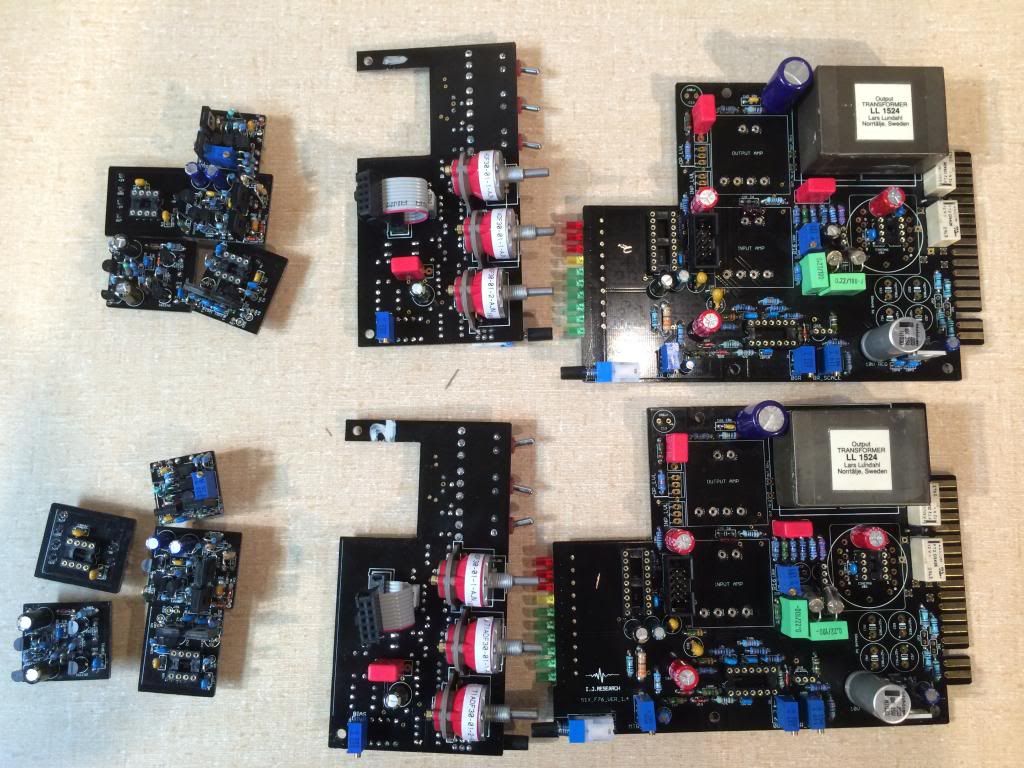
Anyway, I thought I'd post a pic of my albatross DOAs as an example of how not to build them! ;-)

If anyone can suggest what I got wrong that would be good, though my current thinking is just to use a different doa for the input amp for the time being... (FWIW, my current guess is that I installed the BD139s backwards...though now that I think about it, they're placed consistently with respect to the BD139 And BD140 on the IC output amp, and the modules with those amps in, don't smoke, so...)

Has anyone tried alternative DOAs for the input amp, and did they have any problems with them?

I picked up a couple of DIY-990s from hairball a while back which are supposed to be suitable for 24v operation with a couple of resistor swaps so I'm thinking I'll try those at some point...

Cheers,

Kaz
 

Attachments

  • IMG_0093.jpg
    IMG_0093.jpg
    120 KB
Ok, so I think I've isolated the problem with the albatross DOAs, but would appreciate confirmation of this as an issue or not, as I'll be building some new ones at some point, and I'd prefer to get them right this time! ;-)

So after examining the data sheet for the central semi 2N2484, I think that the emitter and collector might be switched with regard to the albatross DOA...

I've attached a grab of the data sheet for reference purposes composited with the top view of the albatross which I believe confirms it. Can anyone else confirm that they had to reverse their 2N2484s?

<edit>

Oh, and what are the chances that I've screwed the other components on the doa? I've ordered some new albatross pcbs, so I can build new ones if I need to, but if I can get away with just replacing the 2N2484s, then that would be awesome...

</edit>

Cheers,

Kaz
 

Attachments

  • Screen Shot 2014-02-19 at 18.41.01.png
    Screen Shot 2014-02-19 at 18.41.01.png
    129.6 KB
taliska said:
I'm hoping that means that Igor's design has saved me from worrying about having fried any components except ones in the DOA path, which would be great if that's true.

Igor's design probably saved your PCB from being damaged, BTW.

And yes, it seems like your 2N2484 has a wrong pinout, i.e. emitter and collector swapped.
If you have any spares, you can put in a new one with the two pins changed. But used some
shrink tube for isolating the crossing leads. Maybe that's it.

Cheers!
 
culteousness1 said:
taliska said:
I'm hoping that means that Igor's design has saved me from worrying about having fried any components except ones in the DOA path, which would be great if that's true.

Igor's design probably saved your PCB from being damaged, BTW.

And yes, it seems like your 2N2484 has a wrong pinout, i.e. emitter and collector swapped.
If you have any spares, you can put in a new one with the two pins changed. But used some
shrink tube for isolating the crossing leads. Maybe that's it.

Cheers!

Thanks for the confirmation. The bizarre thing is that I made the same mistake on my ic output amps too just because I'm using the same part, though for some reason they didn't go up in smoke...

For now, I guess I'm going to try and locate some of the pn2484s that have a better pinout as unfortunately I only order what I need per build...

Oh well...live and learn I guess. Hopefully this will stop someone else from making the same mistake at least! ;-)

Thanks for the help!

Kaz
 
Hi all.

Looking at my F76s again as my grayhills from digikey will be shipping this week, so I should be able to finish my units off and am looking at changing my input/output pots. The ones I've got are citeks that I ordered from Farnell in an attempt to mimic the original BOM, but they ended up being a bit tight fitting and I want to use something smaller.

Anyway, I've been looking around and found some potentially great pots from alpha (small and 5% tolerance!), but I'm a bit concerned about their power rating.

Can anyone tell me what minimum power rating I can get away with for the input/output pots?

I've looked at the audio schematic and it seems like they're just being used as voltage dividers after the THAT1246 and input amp respectively, but that's pretty much where my ability to work out what's going on ends!

I've looked at the THAT1246 data sheet, and it says "The 1240-series devices are typically capable of supplying 25 mA into a short circuit", but obviously that's the short circuit case they're talking about and I don't know what that says about normal operation. Assuming straightforward usage, the THAT1246 is probably configured for -6 dB operation. The data sheet also says: "For example, with ±18 V supply rails, the 1240-series parts have a maximum output signal swing of +23 dBu". Now I don't really know my decibel related units at all, so I just had to google for a calculator like this one: http://www.sengpielaudio.com/calculator-db-volt.htm and type in some numbers which gave me 30.947147054 volts peak to peak. Now I know that P = IV, so that suggests that power = 31 * 0.025 for the short circuit case, which is 0.775 watts but that seems pretty huge. Can anyone help me with the methodology? I'd rather know how to work this stuff out so that I can feel confident about the result rather than just choosing a suitably big potentiometer with regards to power rating and trusting to luck...

I've also had a think about the output of the IJ input amp stage, but I'm at a loss with this one unfortunately. Help on what power rating the pot should have would be appreciated...

It seems like the smaller ones have lower power ratings, so I just want to make sure they can handle it. Obviously bigger power rated pots are available, but they tend to be larger in size too...

FYI, the ones I'm looking at are these: http://uk.mouser.com/ProductDetail/Alpha-Taiwan/RV120F-10-15F-A10K/?qs=%2fha2pyFadugrQN9O93rLvSvPxd4VhM3GzU2Z7E8cvnKWhZmlVeObpw%3d%3d

but notice that their power rating is only 40 mW (but their tolerance is 5%!).

Thanks for any and all help,

Kaz
 
taliska said:
"For example, with ±18 V supply rails, the 1240-series parts have a maximum output signal swing of +23 dBu". Now I don't really know my decibel related units at all, so I just had to google for a calculator like this one: http://www.sengpielaudio.com/calculator-db-volt.htm and type in some numbers which gave me 30.947147054 volts peak to peak.
..giving a max.15.5V peak voltage across the pot. The 10Klog pot will need a power rating of at least 15.5V^2/10Kohms=0.024W, so your 40mW rated pot will do.
"The 1240-series devices are typically capable of supplying 25 mA into a short circuit" tells you the chips max.drive ability. The min.resistive load to not exceed the chips limits would be 15.5V/0.025A=620R. Your 10K input volume pot in its CW position is in parallel to the series connected resistors R6 and R8, giving 1/(1/10000+1/(27000+10000))=7872R, so no problem expected.
I've also had a think about the output of the IJ input amp stage, but I'm at a loss with this one unfortunately. Help on what power rating the pot should have would be appreciated...
Output voltage of the preceding stage will not be higher than its supply voltage. Worst case steady clipped signal might be (more unlikely, there will be diode drops within the preceding amp stage) at the +18/-18V supply rails, the pots min.required power rating would be 18V^2/the pots resistive value, maybe again 10K, giving 0.0324W. Again your 40mW rated pot would do, if its example value would be 10K. Just substitute your values for voltage and selected pots resistance with previous example values to run your numbers.
 
Harpo said:
taliska said:
"For example, with ±18 V supply rails, the 1240-series parts have a maximum output signal swing of +23 dBu". Now I don't really know my decibel related units at all, so I just had to google for a calculator like this one: http://www.sengpielaudio.com/calculator-db-volt.htm and type in some numbers which gave me 30.947147054 volts peak to peak.
..giving a max.15.5V peak voltage across the pot. The 10Klog pot will need a power rating of at least 15.5V^2/10Kohms=0.024W, so your 40mW rated pot will do.
"The 1240-series devices are typically capable of supplying 25 mA into a short circuit" tells you the chips max.drive ability. The min.resistive load to not exceed the chips limits would be 15.5V/0.025A=620R. Your 10K input volume pot in its CW position is in parallel to the series connected resistors R6 and R8, giving 1/(1/10000+1/(27000+10000))=7872R, so no problem expected.
I've also had a think about the output of the IJ input amp stage, but I'm at a loss with this one unfortunately. Help on what power rating the pot should have would be appreciated...
Output voltage of the preceding stage will not be higher than its supply voltage. Worst case steady clipped signal might be (more unlikely, there will be diode drops within the preceding amp stage) at the +18/-18V supply rails, the pots min.required power rating would be 18V^2/the pots resistive value, maybe again 10K, giving 0.0324W. Again your 40mW rated pot would do, if its example value would be 10K. Just substitute your values for voltage and selected pots resistance with previous example values to run your numbers.

This is really great. Thanks for the guidance Harpo!

I completely failed to notice the max. voltage across the pot will be the half wave (must have been half asleep).

The rest of your calculation seems to be from P = IV & I = V / R, which gives P = V * (V/R), which is obviously just P = V^2/R. I'm new enough to this stuff that I'm struggling to think things through properly, so I really appreciate the pointers.

So, as you said, the 10K log pot should be fine for the input control, as the balanced line receiver is only running at +/-16v anyway. Just for others building this, here's a link to the pot in question which is nice and small with good tolerances.

http://uk.mouser.com/ProductDetail/Alpha-Taiwan/RV120F-10-15F-A10K/?qs=%2fha2pyFadugrQN9O93rLvSvPxd4VhM3GzU2Z7E8cvnKWhZmlVeObpw%3d%3d

The output pot comes after the input DOA, which in my 51x rack will be running at +/-24V, so I think using your logic and calculations that comes out a bit too high to use the same pot as the input pot. 24^2/10000 = 0.0576W. Luckily, I've already ordered and received some replacement pots which are suitable to use instead. They're a bit more expensive, but they're nice and small with 1.5W ratings and 10% tolerance, so I'm going to use those for the output controls.

For the benefit of other builders, the other 10K pots I'm going to use for the output control are:

http://uk.farnell.com/jsp/search/productdetail.jsp?id=8795762&Ntt=8795762

Notice that the heading on that linked pot says linear, but that the description and product code confirms that it's actually a log pot. I've got pots like these ones (vishay/sfernice PRV6s) in the past from mouser for the EQN build, so you can probably find them there if you want to get all the pots for the project in the one place (I generally do all my ordering with mouser because their project management stuff is better than farnells, but got them from farnell in this case as it was just a small order to make up for my own mistakes!).

Anyway, thanks again for the help Harpo. With any luck I'll have my two F76s running by the end of the weekend! ;)

Kaz
 
Finally built my stereo F76 modules.

Definitely read Chunger's excellent advice on http://studio939.blogspot.com/2012/08/ij-research-f76-compressor-build.html it helps a lot.  Build is straightforward, but having the pictorial guide and suggestions really helped with the fit.

Here is my build so far.  Sill missing some parts, but I am awaiting them eagerly.
B5F2F616-EABE-4382-BBE9-69E8A256C568_zpsvky6pqvq.jpg


Builders that bought from Ramshackles are lucky, the service is better, they get fast shipping from Ramshackles and the board are nice.

PS:  If there are remaining poor souls that bought the kit from Igor, I have a list of the missing components in that kit.  PM me and I will provide that list, which will save you some time.
 
Thanks for the BOM updates Bruce.
Igor seems to have been a little lax in the accuracy of BOM's and I have not yet built all his projects that I sell boards for, so if you do find discrepancies or odd bits that you dont understand please give me a shout and I will have a look at it.

Also, if you are building from an old version of the docs, do have a look on our website at the docs - we have updated docs/easy-to-read BOM's for most of the projects and on some projects there are additional docs that Igor didnt release initially.

We also maintain & update a 'hard-to-find-parts' and replacements guide so have a look there (and give us more suggestions!)

Chungers guide(s) are really awesome, so this project is lucky to have one for it.
 
Adjusting my "Bias" I find I am a bit confused.  The idea if I understand it is to do the following:

Feed it a -20dB signal
Max the input
Adjust Attack for Min (fastest? right?)
Adjust Release for Max (slowest? right?)
Adjust output for a 1.23V RMS

THEN
install the 2 FETs and adjust the BIAS trimmer for -1dB.

The problem I am having is the confusing use of dB scales.

Am I always using 0dB=1.228V RMS?
in that case the Bias would be adjusted to output 1.094V RMS and the input signal would be 0.123V RMS
That is what I have done for now.

Or should I be using the other scale in which case I output +4dB (1.228V RMS)
and the Bias would be adjusted to output .690V RMS and the input signal would be 0.078V RMS


slegg said:
Hi everybody,

I've got a question .... for Cascode OPamp, 2SK170 BL or GL ?

Thanks thanks !!

I used GR...seemed to be what Chunger had when he built his F76 and his kit came straight from Igor...so...
 
Thanks taliska,
I'll build one with BL and one with GR. I'll tell you the difference if I hear it !!!!
 
Hello all!  i have successfully built 2 from igor's kits.  i am now sourcing parts to build another 2 from igor's pcb.

1.  does anyone have a US source for the ribbon cable and connectors?  i'm having a hard time finding those.

2.  does anyone have a US source for the toggle switches?  i can't find a US source for the MULTICOMP switches in the BOM.  these look close,  but I'm unsure if they will fit.
http://www.mouser.com/ProductDetail/NKK-Switches/M2012S2A2G30/?qs=sGAEpiMZZMvudeGI7i40XM9lbS6CChc2ssS0Egwjy%252bw%3d

3.  same with the LEDs... anyone gotten those flat leds from a US source?

4.  the IGOR bom lists 10k pot for output.  the 1176f schem lists 100k pot.  curious why the f76 uses a 10k pot. 

5.  I'd like to make the controls function as close as possible to a revF, so i'm planning on using pots for the attack/release (5M and 25k).  i understand it as the f76 has SLOW at the CW position.  To make these function like an 1176 so that FAST is at CW,  is it as simple as reversing the connections?

6.  the bom lists TL074P for IC6.  will any TL074 work there? ( can't find a P version ).  Like this one?
http://www.mouser.com/ProductDetail/Texas-Instruments/TL074ACN/?qs=sGAEpiMZZMtCHixnSjNA6P3Ssczg4flJ4b0Fos4RBXg%3d

Thanks much everyone.
 
qmp audio said:
Hello all!  i have successfully built 2 from igor's kits.  i am now sourcing parts to build another 2 from igor's pcb.

1.  does anyone have a US source for the ribbon cable and connectors?  i'm having a hard time finding those.

I got mine from Farnell in the UK, but was feeling helpful so I tried finding some on mouser. I think this is what you need for the header:

http://uk.mouser.com/ProductDetail/FCI/66506-001LF/?qs=sGAEpiMZZMs%252bGHln7q6pmxAVkKtOEC39x%252bMZRvPovBI%3d

And this would be the female part:

http://uk.mouser.com/ProductDetail/FCI/66900-310LF/?qs=sGAEpiMZZMs%252bGHln7q6pmxAVkKtOEC3902NCbcFrx9I%3d

And perhaps this for the cable (or something like it!):

http://uk.mouser.com/ProductDetail/3M-Electronic-Solutions-Division/3365-10-CUT-LENGTH/?qs=sGAEpiMZZMsJiFh04Lj2rqE9WUkL5fzVjO%252b525M71nY%3d

But obviously I haven't used those myself, so you should check the datasheets just to be sure. ;)

2.  does anyone have a US source for the toggle switches?  i can't find a US source for the MULTICOMP switches in the BOM.  these look close,  but I'm unsure if they will fit.
http://www.mouser.com/ProductDetail/NKK-Switches/M2012S2A2G30/?qs=sGAEpiMZZMvudeGI7i40XM9lbS6CChc2ssS0Egwjy%252bw%3d

I seem to remember there being some digikey part numbers in the original BOM for those, but haven't got it to hand myself...

Kaz
 
qmp audio said:
2.  does anyone have a US source for the toggle switches?  i can't find a US source for the MULTICOMP switches in the BOM.  these look close,  but I'm unsure if they will fit.
http://www.mouser.com/ProductDetail/NKK-Switches/M2012S2A2G30/?qs=sGAEpiMZZMvudeGI7i40XM9lbS6CChc2ssS0Egwjy%252bw%3d

Looking very very closely at Chunger's build photos I think I was able to determine a proper part and found these switches on Mouser:

http://www.mouser.com/ProductDetail/CK-Components/E101MD1AGE/?qs=%2fha2pyFadui7fmXg5D5VHzeYUMlC3Wv6jFoQNk4twq0%3d

Maybe take a look at the datasheet and measure the lead spacing?  I'd do it myself but I'm at work and the PCBs are at home.
 
Thanks!  Very helpful.  What value for output pots did any of you use?  The BOM states 10k,  but the digikey PN txt lists a 100k.  Igor mentioned in this thread he used 10k w/ a resistor for <40db attenuation.  I suppose i could try both and see which I like better.
 
qmp audio said:
Thanks!  Very helpful.  What value for output pots did any of you use?  The BOM states 10k,  but the digikey PN txt lists a 100k.  Igor mentioned in this thread he used 10k w/ a resistor for <40db attenuation.  I suppose i could try both and see which I like better.

The two I built used 10K logs for input and output, and grayhills for everything else, so strictly by the book and work perfectly and sound great to me.

I love these compressors...just wish I had a need for more than two of them! ;)
 
mtw said:
qmp audio said:
2.  does anyone have a US source for the toggle switches?  i can't find a US source for the MULTICOMP switches in the BOM.  these look close,  but I'm unsure if they will fit.
http://www.mouser.com/ProductDetail/NKK-Switches/M2012S2A2G30/?qs=sGAEpiMZZMvudeGI7i40XM9lbS6CChc2ssS0Egwjy%252bw%3d

Looking very very closely at Chunger's build photos I think I was able to determine a proper part and found these switches on Mouser:

http://www.mouser.com/ProductDetail/CK-Components/E101MD1AGE/?qs=%2fha2pyFadui7fmXg5D5VHzeYUMlC3Wv6jFoQNk4twq0%3d

Maybe take a look at the datasheet and measure the lead spacing?  I'd do it myself but I'm at work and the PCBs are at home.

OK - I took a look at the data sheet and measured the holes on the PCB - these should fit.
 
Back
Top