


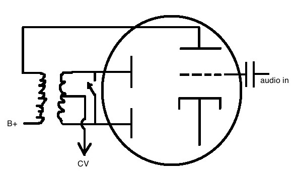
Here's a drawing of a typical 1940's era compressor side chain, with a switch I've not seen implemented. We have a triode/dual diode tube that amplifies the audio, and gives rectification through the secondary of the plate transformer at a 1:1 ratio, with the control voltage taken from the center tap.
The part I've not seen is the switch to short the rectifier plates together. In practice it's sort of bypass, but I'm still getting some control voltage output at a much lower level. It doesn't thump audibly at all, and that may be the sole reason for this approach.
Would you call this bypass? With a change to half wave inductively limited rectification of leakage and secondary imbalance components?
I've not shown it, but the switch is a DPDT, and the other section turns a pilot light on and off, off when the rectifier plates are tied together. I'm looking at four of this particular limiter at the same time, and they all have this circuit.


![Soldering Iron Kit, 120W LED Digital Advanced Solder Iron Soldering Gun kit, 110V Welding Tools, Smart Temperature Control [356℉-932℉], Extra 5pcs Tips, Auto Sleep, Temp Calibration, Orange](https://m.media-amazon.com/images/I/51sFKu9SdeL._SL500_.jpg)


