Potato Cakes
Well-known member
Hello, everyone,
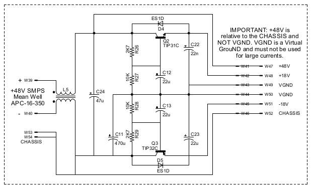
A long standing issue I have been having with some custom builds is trying to supply power to single source and bipolar circuits with a single power supply. So I decided to design my own to suit my purpose and hopefully others as well. I've attached my chicken scratch schematic based on what I have experienced, read about, and seen on many other builds. I'm taking a single source SMPS and filtering it before it goes anywhere else. Then it's split between the single source regulator and the rail splitter that feeds the bipolar regulators. There is also a tap for phantom power. I'm trying to keep the board as compact as possible but still allow for a wide range of capacitors to suit each build's need by making the lead spacing 5mm. I am using a LM317HV for the 48V regulation as I have been running my Neve builds anywhere from 36-40V since the transistors used can handle anywhere from 60-80V rails and I just need to change a few cap values to handle the extra voltage.
Right now I have two capacitors parallel for per rail power reservoir to allow for higher capacitance with needing large expense caps. This might be more overkill that what is usually desired. I may scratch that if needed to save space as I'm wanting fit this in as compact of PCB as possible.
The one thing I am not sure of is the phantom power. I am purposely separating the 0V and ground as I have found doing so for my Neve type builds eliminates the hum I experience with most mics I use, especially dynamics. I've gone through various way to route the grounding and even caused personal injury to myself in the process and the one thing that I found to have worked is keeping the 0V and ground separate. But condenser mics use the ground for +48V reference unless I am mistaken.


![Electronics Soldering Iron Kit, [Upgraded] Soldering Iron 110V 90W LCD Digital Portable Soldering Kit 180-480℃(356-896℉), Welding Tool with ON/OFF Switch, Auto-sleep, Thermostatic Design](https://m.media-amazon.com/images/I/41gRDnlyfJS._SL500_.jpg)


