603 Royer mod advice

GroupDIY Audio Forum

Help Support GroupDIY Audio Forum:

This site may earn a commission from merchant affiliate links, including eBay, Amazon, and others.

Enchilada

Well-known member
Joined
Aug 24, 2011
Messages
323
Location
Australia
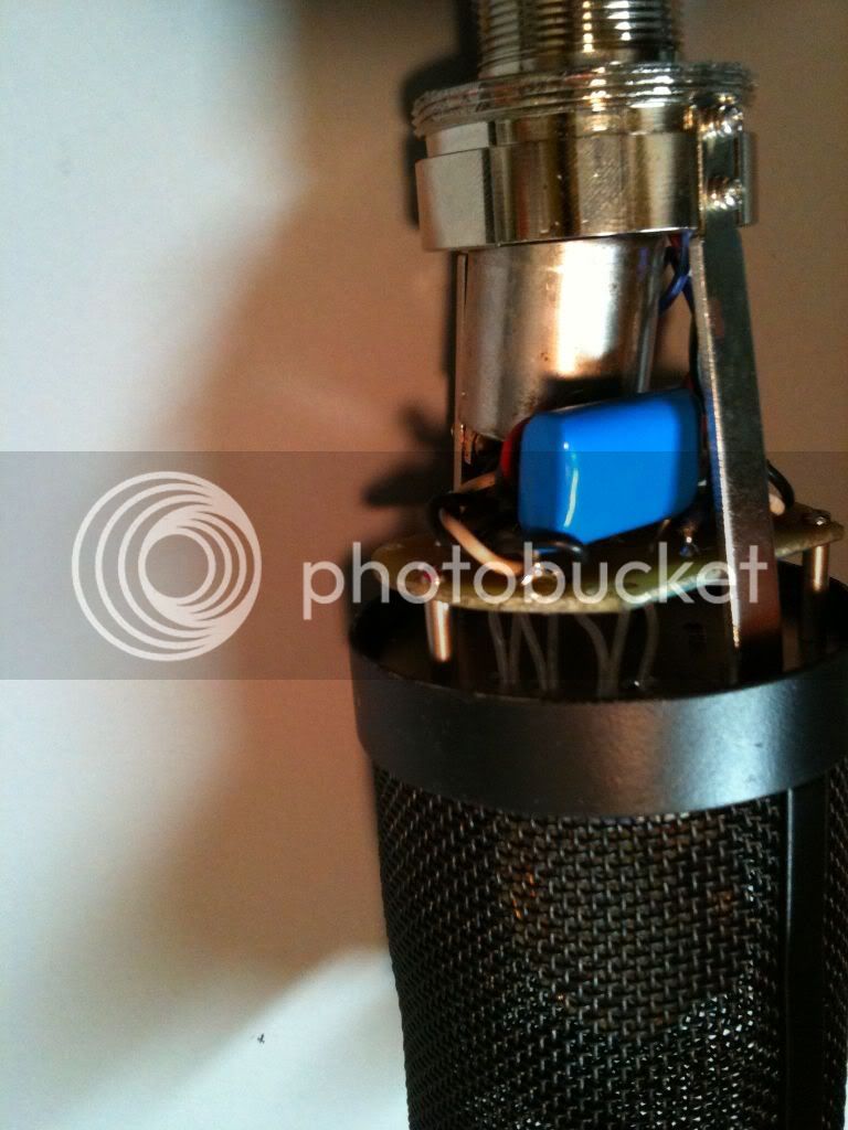
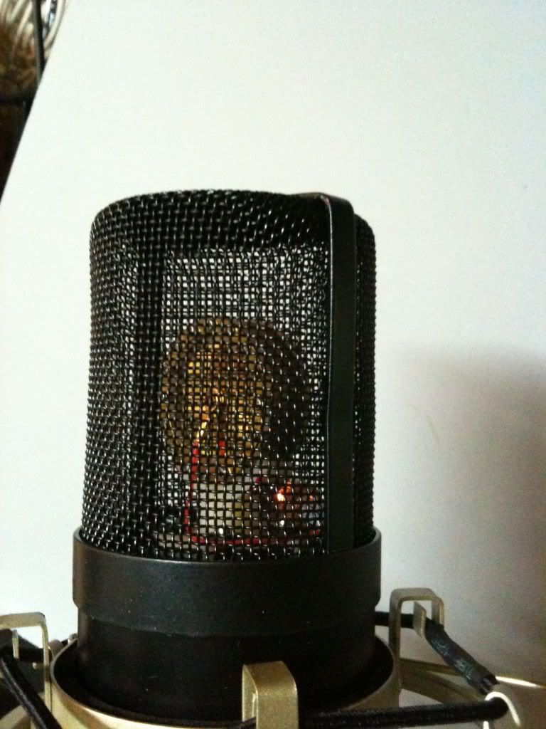
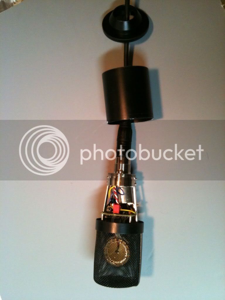
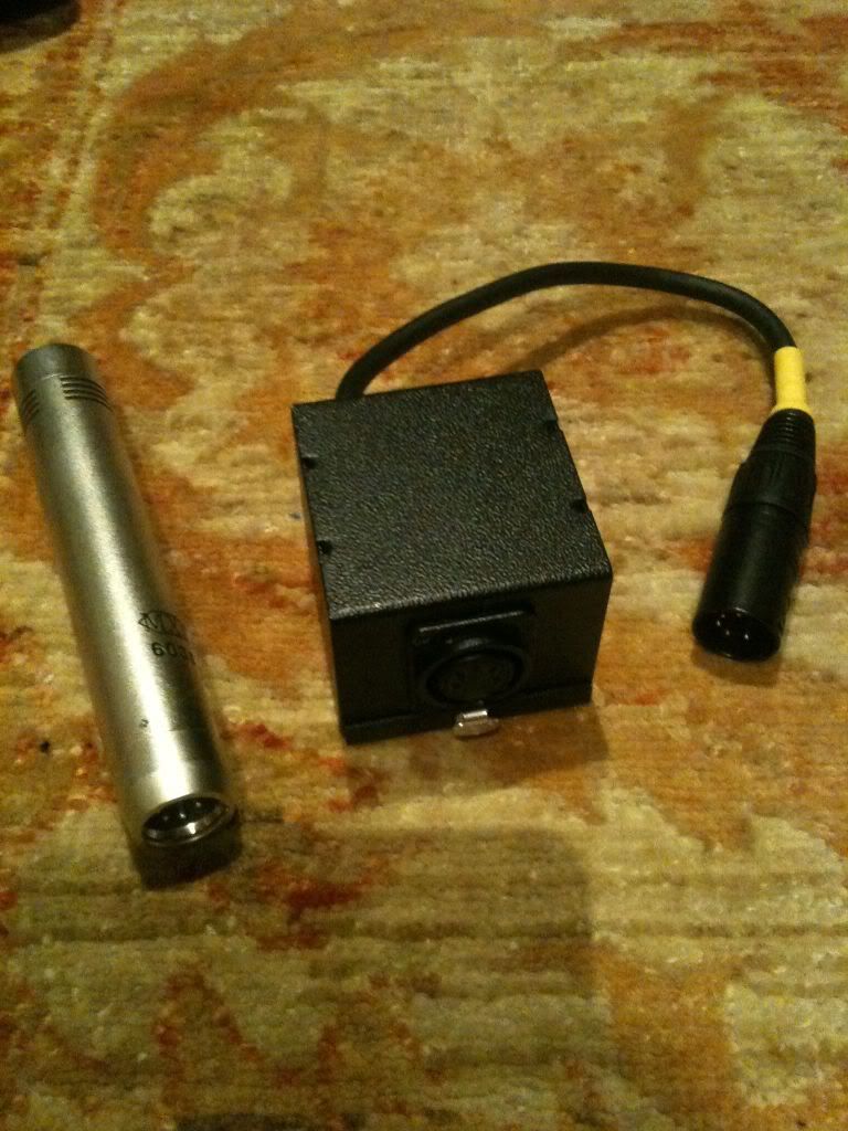
Hey guys, I picked up a couple of NOS 6205 (CV2432) tubes from 1974 for $5 each (and the the guy I bought them from has hundreds more) I was thinking this might be an ideal substitute for the 5840 in a royer mod for my pair of 603s. Are there any modifications I would need to make to the circuit? I did a search an saw someone say "6205 looks to be the same as a 5840 except G3 is not connected to cathode". Does this mean I'll need to connect pin 3 to pin 6?

One more question, how would this go as an input transformer? http://au.element14.com/oep-oxford-electrical-products/a262a7e/transformer-audio-1-1-1-1/dp/1689035?Ntt=1689035
Could I use one of these transformers sound alright wired in the same way b3groover wired his 1+1:1+1 Lundahl LL1527 in this thread? http://messageboard.tapeop.com/viewtopic.php?t=53130

Thanks guys, any and all comments are appreciated :)
 
I did a pair of these with 5840's As I understand the 6205 is the same tube.  DO IT per the Royer mod.  These mics now kick some serious ass.
 
Hi,
    I've built several  603s with the Royer mod  and a C-60 circuit  - they all sound awesome - great project and not too expensive.... I've used 5840W, 6205s and 5703s , all sound great. I've used the LL 1527xls - just cant say enough about this project. 

here is a link to some pix of some of the 603s I've done

https://picasaweb.google.com/audiophreeek/603Mogami#

EDIT : Link


Good luck , keep us posted 
 
audiophreak said:
Hi,
    I've built several  603s with the Royer mod  and a C-60 circuit  - they all sound awesome - great project and not too expensive.... I've used 5840W, 6205s and 5703s , all sound great. I've used the LL 1527xls - just cant say enough about this project. 

here is a link to some pix of some of the 603s I've done

https://picasaweb.google.com/audiophreeek/603Mogami#


Good luck , keep us posted

Looks like you might be a handy guy to have on this forum for this project!

I think the wiring of the tube will be fairly simple for me, it's more the power supply that I'm worried about. I read elsewhere that the PCB from the 2001 PSU can be used for 603 just with different capacitors. Has anyone built a PSU for the 603 with the 2001 PCB though?

Kris
 
I actualy used the PSU from the 2001 for the 603s, and for me, didnt have any problems .  I'll check tomorrow, but I think the only difference is the value in a couple of lytic  caps ( 2200uf instead of 3300uf  )  or the other way round , and the coupling cap and resistor are added in to the PSU with the Lundahl. 
  One note :  the 82ohm 5w resistor sets the heater voltage , I had to experiment with slightly lower values to get the heater to sit between 6.0 and 6.3vdc -  it depends on what tube you use and varies from tube to tube also  - in one PSU I put a 10w variable 100ohm restistor - ( thats how AKG did it in the PSUs for the C-60 , C-61 and other vintage PSUs I'm sure .
 
I use the same PSU for the SDC 603 and the LDC (MXL 2001) mic.  But in order to do this you need to change the arrangement a little.  You take the big film cap, and a couple of resistors, and the transformer out of the 603 power supply, and put them in a separate little metal box.  That box has a 5 pin connector on it for the SDC and a short (5 inch) cable to another 5 pin xlr male (which plugs into the PSU).  This has the combined benefit of moving the step down transformer out of the box (less potential hum), and letting me carry fewer power supplies (less potential back problems).  I make all the PSU's the same (although I do use the larger caps from the later article for better filtering), and I put a couple of LED's on the board to drain the caps so I wouldn't kill myself opening one up.

When I did this I tried to re-arranged the pinout of the 5 pin cable on the SDC so something non-catastrophic would happen if the SDC was ever plugged directly into the PSU, or the LDC was plugged into the little SDC interface box.    But I can't remember exactly what.

These were my first real DIY projects, and if I did it again today I think I would use an LM317 regulator to do the heater, there is just too much variation in the individual tubes, and it would be just as good, simpler and probably cheaper to build.

I did build one of these PSU using the original layout from the original article, ( self etch, hand drawn in Sharpie!)  but the later ones I re-arranged so I could fit 2 in a single PSU box for stereo use.  (I usually use the 603's as drum overheads).

I have built 4 of these (2 603's, and 2 LDC's 1 in an MXL 2001, and one in a big long MXL "echo tube", which I shortened and did on a little round PCB)
 
Hi,
    The 2001 Royer Mod uses 3x 2200uf 35v caps and 2x 33uf at 160v and 1x 33uf at 100v  ---  the SDC Royer Mod uses 3x 3300uf 35v caps and  2x 47uf at 160v and 1x 47uf at 100v  . 

  Here is a link to pix of my PSUs  and one I did with the 10w variable resistor, the one with the fixed resistor is 61.8R  for the tube I used to get the 6.3vdc on the heater.  Get a switchcraft 5pin panel mount XLR  and the pin insert directly replaces the 3pin that comes with the  mic.  I also used a 1000mA Wall Wart from Jameco with a 4pin XLR for power so absolutely no problems with hum or buzz ... completely quiet .  also have both Royer schematics up there.

https://photos.app.goo.gl/PpSmPj2qq17WTX1j8

EDIT : NEW LINK
 
It seems to me you could use an MXL mic like the 440 or 990, and put all the electronics inside the housing, avoiding the need to have the output transformer in the PSU. These mics use the same capsule as the 603, just mounted for side-address.
That way you might be able to use the same PSU for the LDC and SDCs.

Couldn't view your site audiophreak, but nice ideas.
 
The wall wart sounds like a great idea, i have never found a center tapped one that didn't have the center tap so far off center that it induced noise into the ground.

Here are some pics of what I did.  If you want the eagle files for the royer design I would be glad to send them along, although I self etched so they are not "board house ready".

Power supplies, a dual, and a small one.  I can actually fit two of the new boards into the small size, but have not done it yet.

IMG_0203.jpg


My hand drawn PSU board, first one I did

IMG_0224.jpg

IMG_0226.jpg


Hand drawn card for the MXL 2001
IMG_0257.jpg


One of the little round boards for the LDC mic
IMG_0467.jpg

IMG_0480.jpg

IMG_0465.jpg


One of the interface boxes, and the 603 that goes with it
IMG_0208.jpg


You can see the tube glowing behind the capsule in one of the shots, I put it up there because it is cute, and shortens the capsule to grid connection.

I really love the LDC mics, I use them all over the place.  I have never really fallen in love with the SDC ones, but I am still trying to figure out what they are good for.  I think maybe the capsules on the SDC's are not as nice as they could be (luck of the draw perhaps).


Update:  I wanted to note that I changed the transformer in the Royermod 1 to be a beyer 1:10 mic transformer backwards.  The 1:4 made the mic way to "hot"  (signal not heat) and I think may have overloaded the tube.  In any case I love it the new way.
 
tchgtr said:
It seems to me you could use an MXL mic like the 440 or 990, and put all the electronics inside the housing, avoiding the need to have the output transformer in the PSU. These mics use the same capsule as the 603, just mounted for side-address.
That way you might be able to use the same PSU for the LDC and SDCs.

Couldn't view your site audiophreak, but nice ideas.


  Hi,  I'm not sure why you coulnt open the link , created on a diff computer .,  works here at home too ... I'll edeit and repost.

  I'm very newb  , I dont completely  understand the circuits , but from the articles , the 2001 mod is a Common Cathode , and the 603 is a Cathode Follower . The PSU requirements are the same for both, the different values in the caps in the PSU ( I read ) were for better filtering ?  anyway , I've used the one for 2001 for both with no problems for 3 years used often. 


bruce0 said:
The wall wart sounds like a great idea, i have never found a center tapped one that didn't have the center tap so far off center that it induced noise into the ground.

  It works out well  ( but usually need to gaffe tape the wall wart to a power strip  , it dosent need  a centertap, just 24vac @ 1A.


bruce0 said:
Here are some pics of what I did.  If you want the eagle files for the royer design I would be glad to send them along, although I self etched so they are not "board house ready".

Power supplies, a dual, and a small one.  I can actually fit two of the new boards into the small size, but have not done it yet.

  Way cool  .. its always nice seeing how others are building  :)      Thanks for the offer of the files , I've never self etched yet ,  would like to try sometime , but  doesn't look likely soon.

  is that a working dual supply ?  I was helping someone who tried to build a dual PSU for a pair of 603s in a 1U case ... he couldn't get the humm/buzz out .. so I looked at it , couldn't figure it out ,  tried everything ... I coulnt find a 24v seconday at 2A or even 1.5A that would fit in a 1U case , so had to go with two toroids one for each mic ... so this was weird .. with either single mic plugged in in eather channel , it was dead quiet .. but as soon as you plug in the other .. no matter wich one it was, instant humm / buzz ..... tried two diff types of toroids , no matter what position, distance or orientation ... got noise when both mics plugged in.  Then I tried two  Wall Warts ... no noise !!!


bruce0 said:
I really love the LDC mics, I use them all over the place.  I have never really fallen in love with the SDC ones, but I am still trying to figure out what they are good for.  I think maybe the capsules on the SDC's are not as nice as they could be (luck of the draw perhaps).

  I have read that its sometimes hit or miss with the 603s , I think I got lucky with four of them , two with the Lundahls and two with another OT and think they sound beautiful , have had some freq tests done with capsule on , and then just the preamp and its extremely linear.  and the LDCs are very nice indeed  ....... are spectacular with  other capsule choices  ( to my ears )  and if you have the $ 

  EDIT :  b3groover was a great help with this build .. has a great post in TapeOp forum
Enchilada said:
Could I use one of these transformers sound alright wired in the same way b3groover wired his 1+1:1+1 Lundahl LL1527 in this thread? http://messageboard.tapeop.com/viewtopic.php?t=53130


Yes it is a working dual supply.

Here is a link to more photo's

http://s1221.photobucket.com/albums/dd463/Bruce0/Royer%20Mic%20Mods/

I forget what transformer it is, I can pull it apart and look if you want.  It does drive two mic's heaters fine, though as it is unregulated it does drop a little with two hooked up.

The a runs seperately to two different royer PSU boards, both of which are inside.  1 transformer, 2 PSU's.  I think it is a 1 amp transformer or larger.

It is a long box, and so I was able to distance the transformer somewhat from the outputs, and I put some shielding on the back of the XLR lines that loop through the end. (from the 5 pin to the 3 pin), just for good measure.  I have no hum I can hear.

But the little box will actually fit 2 boards pretty easily (I re-arranged the caps so they overlap, one board is upside down.  The problem is getting a 1 amp trafo that will fit.  It will fit, but I like the external wall wart idea.

PSU question....  For the wall wart without center tap....
How do you have this power supply grounded?  Is the only ground the pin 1 on the board that the 3 pin XLR is plugged into?  And how does that not put some nasty waveform on the ground of that board? 

Or if it is ungrounded, then what about those musicians touching the darn thing.  I like a 106V psu sitting on the floor next to a human (some of whom I like) to be safety grounded.  Call me silly (grin)...

But seriously, I am also new to this, is there a way to get at the safety issue with no ground running to the box?  Or the noise issue?


I have 3 power supplies, 2 singles and the dual one.  I never built the little dual one, it was just a tight for no reason, and I have never needed more than 4 at a time.

The  step down transformer in the shorty mic is a backwards mic input transformer from an old Altec mixer, but because it was only 4:1, it made the mic way too hot.  So now I have a little beyerdynamics 10:1 trafo backwards in there, the other one uses the Royer recommended Jensen transformer, as do the 603's.

(FYI... I can't open your picassa link either... Maybe you need to allow everybody to access, (not just logged in users).... I use Photobucket, which seems to work well.)
 
Very cool and  interesting work !!

bruce0 said:
PSU question....  For the wall wart without center tap....
How do you have this power supply grounded?  Is the only ground the pin 1 on the board that the 3 pin XLR is plugged into?  And how does that not put some nasty waveform on the ground of that board? 

Or if it is ungrounded, then what about those musicians touching the darn thing.  I like a 106V psu sitting on the floor next to a human (some of whom I like) to be safety grounded.  Call me silly (grin)...

But seriously, I am also new to this, is there a way to get at the safety issue with no ground running to the box?  Or the noise issue?


Well  .....  I am no Electrician ..  but the way it was explained to me ( and could be completely wrong )  and kinda made sense ,  was that the low voltage AC output from the wall  wart is isolated from earth ground because its a transformer.... right  ?  ...  so pin one shield/ground is not connected to case , just circuit ground, .... so case is isolated from circuit, circuit isolated from Mains by wall wart .... right ?

 
I brought two more 603's today! Well, two Carillon Axis-1's but they're the exact same mic  ::). I had done Gus's mod on the other two and I like them too much so I had to buy another pair for my Royer project. At $49 each it's hard not to though!
 
Enchilada.  On the single side print you show there is a direct short between the two AC inputs.

I think you are looking at a two sided check print.

I found a pdf of the power supply and LDC board this is the bottom layer
 

Attachments

  • TubeMic_PS_TL.pdf
    7.7 KB
Whoops! That could have ended badly  :eek:

I'll take another crack at it tomorrow. I have a pdf of both the top and bottom although I followed the sdc mod schematic for the cap and resistor values.

I would prefer to etch a single sided PCB though because I'm lazy. Also because I have plenty of single sided clad lying around.
 
sorry this is the bottom layer the other was top.

There is also a check print, and a placement... thing, pm me if you want them I can mail them to you.

I don't know what the transformer needs to be, in the LDC Royermod 1 mic, he used a 1 amp transformer 24 Volts.  In the SDC royermod 2 he used 0.6Amp 24V.  Your transformer appears to have 2 1 amp 24v secondaries, so I guess that would easily drive two PSU's.  I think I drive two with a single 1 amp transformer, but as I say I would have to pull it apart to see what the trafo is.

I checked, and my PSU layout in eagle is also two sided.

Also, if you check the schematic, you will see that the royer PSU card has a via (a connection from one side to the other) that may not be obvious.  Took me a while to get that working because I etched it, and at the time I didn't understand what a via was!
 

Attachments

  • TubeMic_PS_BL.pdf
    10.2 KB
I will pull apart the dual supply and look tomorrow.

The single supply uses <http://www.mouser.com/ProductDetail/Xicon/41FK600/?qs=babMXf5%2fnas8eSMgJ7gCVg%3d%3d> which is a hammond 41FK600
which works fine, although both of them had a small noise buzz, which I fixed by tacking down the frame, and tabs with a center punch, which kept the frame from buzzing.

 
I pulled apart the dual supply
The transformer is labeled:
TR241
Input: 100-120V AC 60Hz
Output: 12V+12V AC 1A
Made in China

I looked online and I think it is a Philmore TR241

I don't use the center tap.
I have the two Royer PSU cards in parallel on the 24V AC.

Seems to work fine, I did drill holes in the box it because it got warm, but not very warm.
The fuse has never blown so I guess it doesn't draw over 1 amp.

I will say that the dual power supply is not a great idea.  If I am using it with one mic and want to add a second mic, I have to turn it off and wait for the caps in the unused PSU to drain ( drains very very slow, I put a drain resistor in there, and seemingly forever on the original Royer design).  The problem is, that if you then plug in the second mic, the power supply that was not in use has a good charge in the caps, and you can actually watch the heater get really bright, and then calm down.  This is very bad for the tube, and can substantially shorten it's life (I am told) I think the resistance of the heater increases as it heats up... and that is why a slow ramp is preferable..

One of the nice things about the Royer PSU design is that it ramps up the 6v slowly.  But that only works if it has a mic on when you first start it up, otherwise it just charges up the caps and then provides too much current when the mic is plugged in.


Anyway, the DUAL PSU work, but is not a "flexible" tool because of that limitation (never mind trying to explain this issue that to the helpers).  The right way to use the Royer PSU, is to plug it into the mic, power it up, and let it warm up, use it and then shut it down. You shouldn't power it up, and then plug a mic in... bad for the tubes , and the current through the heater gets too high

From a usability point of view, my preference would be to have small light PSU's, and one for each mic.
 
Back
Top