8 Chnls DIY Tube Mixer question

GroupDIY Audio Forum

Help Support GroupDIY Audio Forum:

This site may earn a commission from merchant affiliate links, including eBay, Amazon, and others.

El Liron

New member
Joined
Jul 27, 2004
Messages
2
Hello!
Ezequiel from Argentina.
i have some UTC A10 ,about 8, and want to build a tube mixer, just volume and pan, 8x2, no eq, no sends, no inserts.i also have 2 UTC A20, i think this ones could be used for the stereo balanced output.
i need to know how to make a stereo buss for summing the 8 channels after volume control, and if with the UTC A10 will have only mic input or both mic-line?
Thank you!
 
That won't help him much, since he wants a stereo mixer with pan controls.

If I have time, I'll sketch up something later, when the boss isn't around, or when I'm home...

In the meantime, this might help:
http://electronicdave.myhosting.net/miscimages/mixnetwork.gif
and
http://music-club.rutgers.edu/headfonz/NYDave/panpot.gif

"RL" in the panpot drawing are the buss input resistors, which are calculated according to the data in the first chart. If you're using, say, a 50K dual pot for the pan control, you use 50K as your figure for "Z" when designing the mixing network.
 
OK... You can use your transformers in whatever preamp or line-amp circuits you like. Here's a simple mixer circuit that should do well with any amps that are designed to work from/into 600 ohms.
8inputmxr.gif


A typical implementation would have the left/right outputs going into the 600-ohm inputs of preamps, with their gain controls acting as the master faders; or, into preamps, followed by master level controls, then line amps.

Good luck!
 
Thanks for the reply!!!
for the panpots i'll need only "left -center left- center - center right - right", so i think it can be a 5 pos rotary or something.
with the UTC A10 can i have both line and mic input???
Thankyou!
ezequiel
 
Well, I don't see why you'd only want 5 positions when it's just as easy to make it continuously variable. But if it's really what you want, this should do:
5pospanswitch.gif

Since the A10 is a mic input transformer, I assumed you'd be building mic preamps with them. You can always add a switchable pad for mic/line input. That's pretty common practice, at least these days. My friend Rick Chinn has a page that tells you all about mic pads:
http://www.uneeda-audio.com/pads/
 
Here's the Ampex, it has left center and right switches, and is active if you have a need for something a bit more ambitious.

never mind, took too long to load.
go here and click on pro audio

http://www.one-electron.com/filing_cab.html
 
i have schematic for a very simple smooth tube sounding summing amp. email me if you want it.
 
[quote author="thestudio"]why was the Ampex Web Site removed ?[/quote]
it's not it's still there..
(or do you mean the URL is missing? - try double keying on the word "here")
Apologies if I have got this wrong
 
NYDave, would it be possible to build two of your 8-channel instant mixers to make a 16 -> 4 -> 2 mixer? The only thing I can think would be an issue is a way to switch channels between the two different mix busses. Would your circuit be able to handle stacking more channels onto it?

Thanks for your help!
 
16 x 2 would be easy; it would just involve recalculating the values of the mixing resistors. In the case of 16 x 2, they would be 4.4k instead of 3.9k. The idea here is that each wiper on the panpot should be working into a 5K load, which is formed by the mixing resistor in series with the mix buss impedance. As you add more channels, the mix buss impedance drops, so the mixing resistor value must increase in order to maintain the same total impedance. The formula is R = (N-1)/(N+1) * Z, where N is the number of channels, and Z is the desired input impedance of the network. So, for 8 channels: 7/9 * 5000 = 3888. For 16 channels: 15/17 * 5000 = 4411.

The output impedance of the mixing network would drop to about 312 ohms; so, if you need the output Z to be around 600 ohms to match the booster amp input, you could build it out with a 270-ohm resistor. Or you could leave it as-is, since it would be a reasonably good match for most mic preamp inputs.

For a "virtual ground" active summing stage, the mix buss impedance is (ideally) zero, so R simply equals Z. You would use 5.1k resistors, in that case.

16 x 4 x 2 is doable, but would require some fancy switching and--depending on whether or not you wanted to be able to assign to both pairs of busses at the same time--possibly scaling up the input Z of the mix networks by a factor of two. If I have time, I'll sketch something for you.
 
I really do thank you much for your time, Dave. Maybe I can turn this into a real project at some point for others to build.

Really all I'm after is a bit of OTB mixing flexibility. 16 outs from the computer go into the mixer. I would like each channel on the mixer to have at least one send (to go to EQ and/or compressor), then back to the fader. From there, the two submix busses will be for stereo effects, like delay and reverb (also with a send each), before going to the final master buss.

I know some may say I want four stereo submix busses instead of two, and I want more sends on each channel, but to tell the truth, I'm being deliberately limiting here. I believe limiting your options forces you to be more creative, which is another reason for going OTB: computer programs make it way to easy to overdo things.

I am thinking a third stereo submix buss would be handy, and something to consider, if only for a little more flexibility.
 
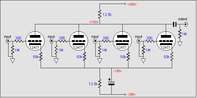
I think this one is really interesting. I know, lots of triodes, but maybe you can do it...

Let´s see... 8 channels, stereo, 8 line amps, that´s something like 24 triodes for a very simple mixer. WOW! Only 12 tubes. it´s not impossible...

I´m thinking 8 triodes at the line amps followed by the pan circuit and then 16 triodes on the summing bus. Maybe two more for the outputs, or 4 triodes for a WCF or a SRPP output.

img51.gif
 
Well, I just heard this kind of circuit sounds great, but I believe you... a simple passive network with a line amp is the way to go!
 
But Dave, if we use 8 triodes as plate followers line amps on the front of the mixer, how can we tune your passive network to work with the high impedance of the plates and the summing amps grids? Will it work ok as a high impedance summing network?

Why did you draw it for 600 in/ 600 out impedance?
 
Or should we use 8 transformers after the line amps and then 2 transformers for the summing amp inputs? LOTS of iron!

simple cathode followers will probably not drive 600ohms, and SRPP/WCF will double the number of triodes on the front end...
 
Well, I just heard this kind of circuit sounds great

"Plate mixing" works great for a couple of inputs--I've used it in guitar amps--but beyond that, it becomes extremely cumbersome.

I think whoever drew that circuit was either smoking the pipe or has a really twisted sense of humor :green: First of all, there's the completely unnecessary bipolar supply. And the 12AT7 is probably one of the worst tubes to use in such a circuit, running open-loop like that. The 12AT7 has certain qualities that make it very suitable for some applications, but it's also a rather nonlinear tube. In other words, distortion will be high.

But Dave, if we use 8 triodes as plate followers line amps on the front of the mixer, how can we tune your passive network to work with the high impedance of the plates and the summing amps grids? Will it work ok as a high impedance summing network?

Sure, it can be scaled for any impedance you like. If you want to drive it directly off tube plates, though, you'll have to scale the impedances way up, and then you get into increased thermal noise from high resistances, high frequency rolloff, etc.

Why did you draw it for 600 in/ 600 out impedance?

Because it seems that every month or so, somebody asks about building a little mixer to use with a bunch of "vintage" preamps, line amps or EQs, which are usually designed to work from/into 600 ohms. For use with more modern equipment, it would be desirable to design for an input impedance of ten times that (or more) and the lowest possible output impedance.
 

Latest posts

Back
Top