8 Microphone Selector Switcher

GroupDIY Audio Forum

Help Support GroupDIY Audio Forum:

This site may earn a commission from merchant affiliate links, including eBay, Amazon, and others.

pablobolche

Well-known member
Joined
May 21, 2009
Messages
98
Location
CHILE
Hello...
I am making an 8 Microphone selector switcher and need some insight...
the plan..

All microphone would be phantom powered...so box would have it's own 48v feeding all 8 microphones at all times. ..this would translate in 70-80 mA@48v..
Switching would be done with relays....with separate +RVolt and Rgnd..
Output will go to a mic splitter transformer and finally out.(not in the picture...)

Now...on the PCB I will have traces to all 8 relays and only one will conect at a time....would these non used traces act as antenna?? Is there a problem doing this??

Regarding posible switching noises...are there any condensors to gnd or stuff I should look into??

Thank You
 

Attachments

  • IMG_20160816_174731.JPG
    IMG_20160816_174731.JPG
    413.1 KB
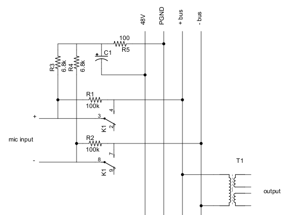
Maybe something like this:

rJqfGpv.png


But I just sketched this up in 10 minutes so it might be complete nonsense.
 
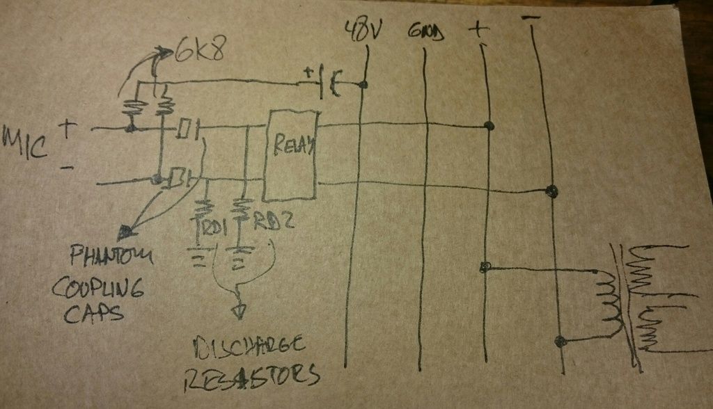
If you absolutely MUST switch at microphone level, make sure to do it at a point where there's no DC superimposed.

That is, after phantom, coupling capacitors, and discharge resistors.

Jakob E.
 
Oka...did some reading in the forum  and found a  sketch from magnetosound...
This should  work right??.....as there should be no DC going in the relays...

IMG_20160817_100513_zps0vvttzpk.jpg


Thanks for all your comments....


great.......

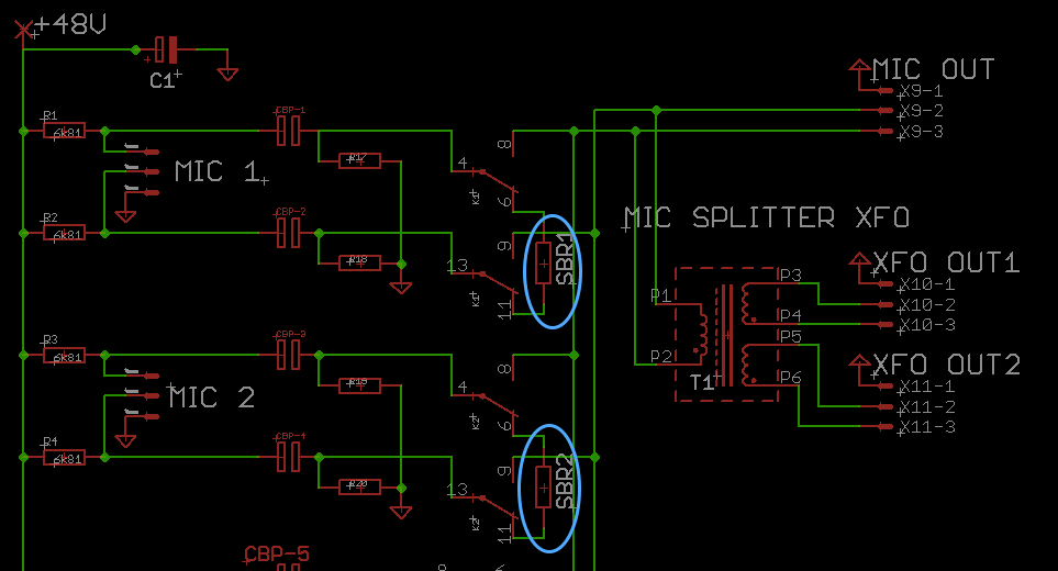
Now if I wanted to use a Direct Mic Out after the relays...and somebody activates phantom power I would have DC on the out from the relays and I would get clicks again...should I repeat the coupling caps/discharge resistors between the MIC OUT and the transformer input?? Or would it be better just not to use Direct Mic Out at all??..

I added a 200 ohms standby resistor for microphone to see 200 ohms right before connecting the transformer input...which should be around 200ohms?? might this help or would it be a bad thing to do??

Captura%20de%20pantalla%202016-08-17%20a%20las%2011.42.19_zpsdywrn3ri.png


pablobolche said:
great.......

Now if I wanted to use a Direct Mic Out after the relays...and somebody activates phantom power I would have DC on the out from the relays and I would get clicks again...should I repeat the coupling caps/discharge resistors between the MIC OUT and the transformer input??

Your schematic says MIC SPLITTER but it is MIC SELECTOR.

SELECTOR is the key in answer to your question.

When you include another cap(s) after the relay contacts this is what will happen. In relay on position (mic selected) when you switch the phantom on, the transient on the output of the cap before the relay will charge the cap after the relay. Therefore you will have DC across the relay contacts. If you turn the relay off (to select another mic) within the time constant set by the caps and the shunt resistors you will get a click. In fact in high gain more likely to be a bang. So you have to include series resistors to increase the charging time of the capacitors after the relay.

If you want to skip among multiple mics in high gain conditions you have no choice but to look into introducing muting into your system.
 
Ok...so Direct post relay Mic Out will not be used....only post transformer outputs...

I appreciate all your coments..

 
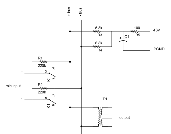
Look ma, no coupling caps:

EfwBpfQ.png


Depend on the mic circuitry I would not be surprised if there were absolutely no pop at all with the above circuit.

The only problem is you would not be able to independently control 48V to each mic.
 
I like the no cap aproach...and the reduced components....
With this cirquit i would have 48v on both sides of the relay..thus no click??
I guess I will give it some thought...

Thanks for your helps

squarewave said:
Look ma, no coupling caps:

EfwBpfQ.png


Depend on the mic circuitry I would not be surprised if there were absolutely no pop at all with the above circuit.

The only problem is you would not be able to independently control 48V to each mic.

 
pablobolche said:
I like the no cap aproach...and the reduced components....
With this cirquit i would have 48v on both sides of the relay..thus no click??
Not exactly. When the mic is switched out, it's voltage will drop considerably. But the mic circuit, whatever it is, is almost always going to be something like a resistor on each input with a capacitor to ground. So when the mic is switched in, it will draw current but because of said resistors, the resulting transient will not be too sharp. At least it will not be more than when you switch on 48V in a conventional mic pre. Actually I think it should be less because R1 and R2 will serve to elevate the mic voltage some depending on how much current it draws.

But honestly I'm not sure what would happen. You would have to just try it. Putting a switch in front of 60dB of gain is going to create some kind of noise. To completely eliminate all noise you would need a muting circuit as someone else already stated.

But if the noise isn't too much, you could use one 2 pole switch to select the mic. No relays. Very simple.

Also, make sure your wires are short and shielded right up to the relays / switch / transformer / etc. I use the 2 conductor snake cable from Redco. I just create a little slit and pull the required wires out leaving the shield intact.
 
Ok....I like the simplicity but kinda don't think Condenser Mics would like to go from low voltaje to high voltage to low.....

What if I just use phantom power on the mics and on the "out side"  of the relays..as I will not use the direct out I just have a mic transformer ....with carefully matched resistors all through... there would be no DC difference on the relay.... their might  be  a tiny disconect while relay changes state....this would click??

thank you for your insights

 
pablobolche said:
What if I just use phantom power on the mics and on the "out side"  of the relays..as I will not use the direct out I just have a mic transformer ....with carefully matched resistors all through... there would be no DC difference on the relay.... their might  be  a tiny disconect while relay changes state....this would click??
The more I think about this, I think you're going to get noise no matter what you do (unless you use a muting circuit to mute, change the switch, then unmute).

If the transient is 10mV, after 60 dB of gain, that's 10V. A 10V spike is going to make a horrible bang. The rationale behind my circuit was that if you can slow down the transient, then it might not make (as much) noise. But honestly I'm not sure my circuit would really work either.

To do this properly, I might first simulate it in LTSpice, then breadboard a test and repeat until I arrived at the best solution.
 
pablobolche said:
With this cirquit i would have 48v on both sides of the relay..thus no click??
That would be true only if there was no current drawn by the mic, as in a dynamic or ribbon, but with a condenser mic, with 220k in series with each leg, the voltage will be close to zero.
 
  The scheme in reply #5 has a cap in the way of the 48V, phantom will never get to the mic.

  As it's transformer coupled to the output, the phantom of the mic pre doesn't matters.

  I'd mute the signal while switching, as the transformer will add a decent amount of CMRR shorting the input should kill pretty good the click (or bang) and protect the transformer from a mismatched switching time or something like that. So, you short the transformer input, switch the current mic out, switch the next mic in, open the transformer short. No caps, each mic could have it's phantom or the transformer could have it (I don't know about switching in and out the phantom for the mic all the time is fine or not, you could be needing a much smaller 48V PS. As problems I'm thinking in some settling time the mic could have till it's in working condition, for fast A/B tests could be a problem.

  For this you do need a timing circuit, probably the easier way to manage is a micro controller but there is no real need for one, a bunch of comparators (with could act as relay drivers as well) and some smart workaround would probably do it. mess boogie has areal neat way of muting while switching relays with FETs muting the signal triggered by relay kickbacks. I don't know exactly how it works dough,

JS
 
This seems like a very complex arrangement, with tradeoffs here and there that could be engineered away (or not).

However, the largest question that remains (at least for me) is "why do any of this at all?" What is the end result that you're trying to achieve? To my knowledge, nobody makes, sells or uses a box that does anything like this, so either we're all silly, or there's some other simpler way to solve the problem that this device addresses.

Eagerly awaiting your illumination...
 
Yes they do and people use it a lot!

http://www.radialeng.com/golddigger.php


Oh and if you want to go the other way.

http://www.radialeng.com/cherrypicker.php
 
Back
Top