A BJT/JFET matching circuit?

GroupDIY Audio Forum

Help Support GroupDIY Audio Forum:

This site may earn a commission from merchant affiliate links, including eBay, Amazon, and others.

Matador

Well-known member
Joined
Feb 25, 2011
Messages
3,114
Location
Bay Area, California
Wanted to get a few opinions.

I have the following matching circuit:

npn_matcher.jpg


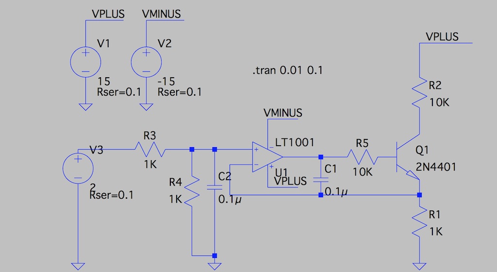
Op-amp is a precision/low offset device.  The voltage divider / cap on the non-inverting input may not be required.

Here is what I was thinking:  when building guitar pedals, I've finding that certain devices are critical in defining the gain staging and distortion characteristics.  A low-ish hfe device in a single stage may sound quite different than a high hfe especially when clipping stages are involved.

I figure that if VBE and hfe are matched closely for these devices (between two pedals) then the sound should be pretty close as well.  If VBE is the same, then the base voltage should be the same in this rig, and if hfe is the same, then the voltage drop across R5 should be the same.

Operation:  if I set the input voltage to 2V, the the op-amp will force 1V across R1 which is 1mA (assuming I measured R1 before hand) through Q1.  The base voltage will be about 0.6-0.8V above 1V, or 1.6-1.8V if the 2N4401 datasheet is to be believed.  With hfe of 100, base current should be 10uA which is 0.1V drop across R5.

My assertion:  if two devices are measured in this rig, and we record a) the opamp output voltage (WRT ground), and b) the base voltage (WRT ground).  Then: if both voltages are the same between two devices, then a) VBE is the same, and b) hfe's are the same (because the currents through R5 are the same).  This can also be done at several current levels just by adjusting V3.

(I actually would like to hook these points up to a ADC and have a small microcontroller board to record this for me).

Does this sound feasible?  Am I missing something?  Perhaps something more basic?
 
Great minds think alike?  :eek:

I wonder:  if VBE is closely matched, would hfe be matched as well?  If memory serves the Ebers-Moll model says that emitter current and base current are both proportional to eVBE, so it stands to reason that two different devices would flow the same collector and base currents if their base-emitter voltages were the same (and hence, hfe would be the same as well).
 
Vbe and hfe are not necessarily related enough to track one to the other, but you can tell us from your results.

Only error you need to control for IMO  is junction temp. As long as device collector voltage is not very high and current low it shouldn't heat up much. You just want them to be same junction temp for closest match, so let them stabilize after you handle them.

JR
 
Matador said:
My assertion:  if two devices are measured in this rig, and we record a) the opamp output voltage (WRT ground), and b) the base voltage (WRT ground). 
That's correct, but you need very high precision to measure the difference. There would be about 6mV difference between a transistor with an hfe of 100 and one with an hfe of 200.
There are more direct ways to evaluate hfe, like injecting a know current into the base and measuring the collector current.
If Vbe matching is your concern, you may try a current-mirror.
 
He can also increase the sensitivity of the base current measurement by making the 10k 100k, or higher.

I spent a lot of time trying to design such that selecting parts is unnecessary, but what other people do with their time and money is up to them. .  8)

JR
 
I match my transistors with the multimeter, just Vbe as a diode and hfe with what it has, not the finest way, but I've build a couple of DOA with this and get offset voltage around or under 1mV...

JohnRoberts said:
I spent a lot of time trying to design such that selecting parts is unnecessary, but what other people do with their time and money is up to them. .  8)
JR

That's why I like the neve 283 and such, no LTP at the input, no matching to do!

JS
 
JohnRoberts said:
He can also increase the sensitivity of the base current measurement by making the 10k 100k, or higher.

I spent a lot of time trying to design such that selecting parts is unnecessary, but what other people do with their time and money is up to them. .  8)

JR
I guess about the last place one needs to match transistors is analog synths.
 
I had started with this circuit:

npn_matcher2.jpg


So this circuit (provided the collectors stay in the common-mode range of the op-amp) should apply the difference between the two VBE's to the base of the DUT.

But to Abbey's point, in most of the devices I tried, this difference was fairly negligible unless the devices were different (like in this simulation), at which point I could measure 0.1V or so.  The datasheets claim a 0.2V spread across temperature and process but obviously this spread isn't very measurable in practice.

I did mock up this circuit, and added the two caps to keep it from oscillating.  It is much better for matching JFET's which vary significantly in VGSoff.  ;D  For matching JFET's, I plugged in one test JFET into the "grounded gate" side, and substituted in different JFET's into the second slot until I found one(s) that measured close to ground at the op-amp output node.
 
Matador said:
So this circuit (provided the collectors stay in the common-mode range of the op-amp) should apply the difference between the two VBE's to the base of the DUT.

But to Abbey's point, in most of the devices I tried, this difference was fairly negligible unless the devices were different (like in this simulation), at which point I could measure 0.1V or so. 
May I suggest that you drive the base of the DUT via a 100:1 resistive divider so you'll be measuring 100's of millivolts instead of fractions. You would have to insert a resistor of suitable value between the base of the reference transistor and ground.
 
abbey road d enfer said:
Matador said:
So this circuit (provided the collectors stay in the common-mode range of the op-amp) should apply the difference between the two VBE's to the base of the DUT.

But to Abbey's point, in most of the devices I tried, this difference was fairly negligible unless the devices were different (like in this simulation), at which point I could measure 0.1V or so. 
May I suggest that you drive the base of the DUT via a 100:1 resistive divider so you'll be measuring 100's of millivolts instead of fractions. You would have to insert a resistor of suitable value between the base of the reference transistor and ground.

Or put R5 higher 1M maybe with a small cap to avoid noise, doing the divider would have 2 resistors to measure with some precision to affect at the end precision.

JS
 
> I guess about the last place one needs to match transistors is analog synths.

As said, "when building guitar pedals, I've finding that certain devices are critical in defining the gain staging and distortion characteristics."

Some forms of musically-acceptable gross distortion happen in "naked" transistor circuits. The kind we threw together long ago when we could not afford to (didn't quite know how to) rig up a circuit that worked with "any" part. And many of the techniques J.R. used to avoid device selection hog-tie the device so it won't make the round mounds of sound, but just clip flat.

What people forget is that Hendrix would sort through a whole box of pedals to find ones he liked. The cheap stuff always varied.

Now when every iPhone and every McMuffin is exactly identical, people expect other gadgets to be exactly identical. The good-old pedal designs don't do that unless you sort.

Yes, whatever happens in a 2N404 fuzz, and happens best when hFE is in a narrow range, could certainly be done with *precision* and *repeatability* with opamps and diodes and other parts. But the good old analog thinkers have moved on, the leading edge is DSP, and the trailing edge is boutique builders building the old stuff the old way but being obsessive.

You could think of it like a violin maker splitting a log and sorting the sticks. He's judging the stuffness weight and damping. Some go in violins, others in viola, still others in the fire. Matador is also judging 2 or 3 numbers and selecting for this or that fuzz type.
 
PRR said:
> I guess about the last place one needs to match transistors is analog synths.

As said, "when building guitar pedals, I've finding that certain devices are critical in defining the gain staging and distortion characteristics."
I stand corrected, I had forgotten this original statement.
Some forms of musically-acceptable gross distortion happen in "naked" transistor circuits.
What people forget is that Hendrix would sort through a whole box of pedals to find ones he liked.
Yes, whatever happens in a 2N404 fuzz, and happens best when hFE is in a narrow range,
That's correct, but is hfe or vbe the only significant parameter? One could argue that Cbc non-linearitiy is probably as important. The problem there is we don't even know what we're looking after.
What makes a good disto pedal? What makes a good wine? Chemical analysis of a great vintage or plonk do not point to one single parameter.
 
abbey road d enfer said:
That's correct, but is hfe or vbe the only significant parameter? One could argue that Cbc non-linearitiy is probably as important. The problem there is we don't even know what we're looking after.

Indeed, I am pre-supposing an answer and working back towards the best question. ;) It's very clear that I can take a single pedal, swap in various transistors into a "fuzz" stage (or any gain stage that has diodes in the feedback path) and get subtle, repeatable changes in distortion characteristics by socketing the transistor and swapping back and forth.  There are probably several parameters at play, but I'd like to start with a handful of "good" ones and a handful of "bad" ones, and see if I can tie the audible differences back to basic transistor parameters.  It might be a rabbit hole with no end but I'm not sure.  This effect still happens (but to a much more subtle degree) amongst transistors of the same part number (and perhaps different manufacturer, etc).

For instance, I'm presupposing that in some stages higher hfe is "detrimental", perhaps due to the bias points not being correct for maximum signal swing in the amplifier (I see many old pedals used high value collector resistors, ostensibly for old lowish gain germanium use), which can cause headroom problems when a modern transistor is substituted.  Maybe with higher hfe the signal spends more time being shunted through diodes as compared to a low hfe one...or perhaps it was all intentional...I don't know.
 
*IF* I can narrow this down to hfe or VBE (or insert some other parameter here) then I can a) have a chance to measure and know I will land in the ball park on a new pedal, and/or b) tweak the circuit to make more "bad" devices sound "good".
 
Matador said:
Indeed, I am pre-supposing an answer and working back towards the best question. ;)
That's the way it should be. Let's not be deterred from a good theory just because the facts do not agree  ;D .
*IF* I can narrow this down to hfe or VBE (or insert some other parameter here) then I can a) have a chance to measure and know I will land in the ball park on a new pedal, and/or b) tweak the circuit to make more "bad" devices sound "good".
I understand you have to start somewhere and certainly measuring the basic transistor parameters is logical. The problem is how to define which objective parameter correlates with "best" when best is purely subjective. I guess your best is not my best.
But in the end if you're satisfied you have identified a parameter that correlates with your best, you'll have made a satisfactory journey.
 
Back
Top