A Noisy Carlsbro Mantis Echo

GroupDIY Audio Forum

Help Support GroupDIY Audio Forum:

This site may earn a commission from merchant affiliate links, including eBay, Amazon, and others.

smilan

Well-known member
Joined
May 29, 2017
Messages
502
hi,
I have an old Carlsbro Mantis echo that is quite noisy.
except from replacing the old electrolytics, can I replace the old 741 op amps with modern op amps?
If so what would be a direct replacement and will operate well with +/- 7.5V supply?
Also I would like to add 104 bypass caps for all the supply rails.
 

Attachments

  • carl mantis delay.jpg
    carl mantis delay.jpg
    1.5 MB
With bypass caps you could put "modern" op amps in there. But the trusty TL071 would be a good replacement. Going for that extra little bit of noise improvement could be quite pointless since this circuit prone to be a little noisey regardless of what you do. I would swap in the TL071 and see what happends.

Also, make sure you get the right level through it. Too low and you're wasting valuable headroom in this circuit. Try running some signal through it and adjust upward until the distortion is too much. Try a slow compression in front. Another trick is to reduce lows going in with like a -6dB shelf at 500Hz and then do the exact opposite on the way out. That will reduce the required dynamic range and therefore improve noise a little. Of course this requires extra gear but it could just be using a few extra channels on your mixer that aren't being used anyway and hey, if you're messing around with an old circuit like this then clearly you don't mind going the extra mile.
 
squarewave said:
With bypass caps you could put "modern" op amps in there. But the trusty TL071 would be a good replacement. Going for that extra little bit of noise improvement could be quite pointless since this circuit prone to be a little noisey regardless of what you do. I would swap in the TL071 and see what happends.
Thanks, I'll go with TL071
One more thing, there's a way to tune the four trimmers on the delay circuit?
 

Attachments

  • trimmers.jpg
    trimmers.jpg
    440 KB
I've replaced all the 741s with TL071 and replaced all the electrolytics.

The only problem remains is the PSU that is way out of specs.
on the output from the diode bridge I have 8.45V, on the +7.5V rail I have 6.28V and on the negative 7.5V rail I have only -4.13V.
I've checked the values of all the resistors on the PSU board and all of them tested pretty close to their original values.
I've also replaced the LM723 with another one with no change.
There's a way to tune  the voltages coming out of this PSU?
When I tested the circuit with an external lab PSU it worked as is should with very low noise.

Schematic:
https://groupdiy.com/index.php?action=dlattach;topic=77203.0;attach=79417
 
smilan said:
The only problem remains is the PSU that is way out of specs.
on the output from the diode bridge I have 8.45V, on the +7.5V rail I have 6.28V and on the negative 7.5V rail I have only -4.13V.
I've checked the values of all the resistors on the PSU board and all of them tested pretty close to their original values.
I've also replaced the LM723 with another one with no change.
There's a way to tune  the voltages coming out of this PSU?
I suspect either the transformer, the reservoir cap or the diode bridge is defective. What is the AC voltage at the xfmr secondary?
 
smilan said:
That would result in about 16Vdc at the reservoir cap (C2).
Clearly that is not enough for the LM723, that needs about 18V to regulate at 15.
The mains xfmr is rated at 240Vac (2x120) for 2x12V output.
That is strange. That would make about 35V before the regulator; a lot of wasted energy and a lot of heat dissipated by the regulator.
I don't think it would work corerctly with the secondaries in parallels.
There are not many solutions.
Use a step-up autoformer with a 220V inputand a 240V output; I don't know if these exist anymore.
Replace the mains xfmr with one that delivers the goods; that would probably be one with a 15V secondary.
Decrease the regulated voltage to a value that allows regulation to work, by decreasing R4. You could use a  5k trimmer in series with a 2k2 for adjustment until noise goes away.
 
Thanks, do you think it will be better to build a new power supply based on a double 12V secondaries and LM317/LM337 regulators?
 
smilan said:
Thanks, do you think it will be better to build a new power supply based on a double 12V secondaries and LM317/LM337 regulators?
The LM723 is an old design, but still adequate in the context of a unit that will never be pristine in terms of noise. I don't think the problem you have justifies such a significant redesign. I would just try to make the unregulated voltage correct.
 
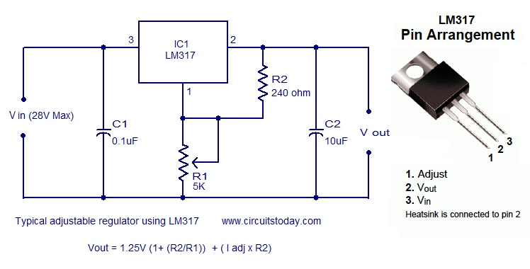
I've ended up rebuilding half of the PSU, I installed a new power transformer, a double 18V / 1A secondarys and used one half of it. Than I built this circuit:
LM317-typical-adjustable-regulator-ckt.png

And connected the regulated DC output to C2 just before the 723 input.
Increasing the value of C4 and C5 to 2000uF reduced the hum drastically .
Now the unit sounds good, but it's still noisy, (not as before).
Do you think increasing the values of C6, C26, C27 or other capacitors will reduce more noise?
Here's a recording of this echo:
https://drive.google.com/file/d/11qxt_948XSH7o8atuzPLfHQuIPesz33F/view?usp=sharing
 
smilan said:
I've ended up rebuilding half of the PSU, I installed a new power transformer, a double 18V / 1A secondarys and used one half of it. Than I built this circuit:
LM317-typical-adjustable-regulator-ckt.png

And connected the regulated DC output to C2 just before the 723 input.
Are you sure you have put a sufficient capacitor before the LM317. Just the 0.1 uf is not enough. I assume you use a bridge rectifier.

Increasing the value of C4 and C5 to 2000uF reduced the hum drastically .
You shouldn't need to do that.

Here's a recording of this echo:
https://drive.google.com/file/d/11qxt_948XSH7o8atuzPLfHQuIPesz33F/view?usp=sharing
There's some hum in the background that shouldn't be there. The hiss is normal with BBD's.
 
abbey road d enfer said:
Are you sure you have put a sufficient capacitor before the LM317. Just the 0.1 uf is not enough. I assume you use a bridge rectifier.
Thanks, yes, of course there's a bridge rectifier before the LM317.
Besides the 0.1uF, what value of capacitance I should put there?
 

Latest posts

Back
Top