Steve Hogan said:
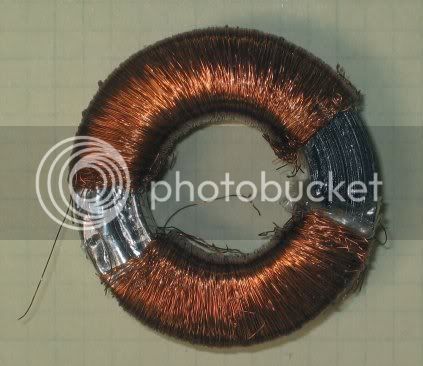
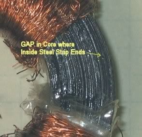
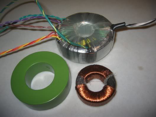
...we are just now making the cores to make the new transformer prototypes. Watch this space as I figure it out.
The cores for the new transformers were wound this morning, are being annealed tonight and will be coated tomorrow.
I expect to wind the first articles tomorrow.
Today I opened up Matt McGlynn's '84 unit. I am amazed at the general quality of the parts used in this preamp.
One would be hard pressed to make the chassis alone with the machined front panel for the money that these cost. I see decent PC boards, a lot of decent parts including Wima and Roederstein caps. Most electrolytic caps are Rubycon 105C types. My initial impression is that there is an awful lot of stuff in this box for the money. All this is before I powered it up. -- Lighted pushbuttons -- impressive. there is no way you could even buy the parts in this box for what they cost.
OK, so my initial impression is that this box is well worth putting some additional money into it to really upgrade it into a very decent mic preamp.
Here's what I found so far in the power supply. First of all, the Power supply PCB layout is OK on the 48V and 24 Volt outputs. The Bipolar 12 Volts had some ripple which doesn't immediately make sense, since the PCB layout appears to be OK. There is one connection that doesn't seem right to me. The 24V and 48V supplies are grounded to the chassis via the screw nearest the power transformer. The Bipolar 12Volt ground, however, is attached to a different chassis standoff. This may cause a problematic loop, because the Bipolar 12 Volt supply does connect to the 24 Volt circuitry and the grounds should be grounded in the same place. It looks like the ground connectin is made with a zero Ohm resistor (jumper) so it looks like it may be easy to get the bipolar supply on the same ground as the rest of the preamp. More experiments needed.
At 120Volts input, the Phantom supply filter cap has about 61 Volts on it. At 10% high line it measures 69Volts and the cap is 63 volts. I will be replacing that 100uF/63V input filter cap with a 220uF/100V Nichicon HE long life, low impedance 105C cap. I will be using some Nichicon HE series caps and some Panasonic caps in this project because the Panasonic FM caps I usually use are not available in all the values/voltages/case sizes that I need to properly fit in the power supply PCB. The Nichicons are excellent and inexpensive. The main filter caps in any power supply take the most abuse due to the high-current pulses from the rectifiers and the heating caused by the ripple current, so these premium (but still very reasonably priced) caps are the right choice in this location. The Factory Rubycons are 105C but are not the long-life types. The remaining factory Rubycons don't get stressed nearly as much as the main input filter caps, so they will work fine when they are just acting as filtering on the regulated supply.
The Filter caps on the 24 Volt supply run at 34 Volts at 120 Vac line and reach 39 Volts with 132 Vac high line. I will be replacing these 35 Volt caps with the long-life 105C 50 Volt parts, which is the next voltage up from 35. There will be less total capacitance on the input filter caps, which is actually a good thing for reasons I will explain below. On the 84 (and probably the '73) there are two 2200uF/35 Volt filter caps (4400uF total) which will be replaced with a maximum of three 1200uF/50V (3600uF total). This is actually way more than is necessary due to the fact that these caps are pre-regulator. Having really high capacitance in this position makes the current pulses from the rectifier extraordinarily high, which may be another factor in the hum being picked up by the circuitry. Smaller filter caps have more pre-regulator ripple, but the current pulses are longer and lower in amplitude. It is a common mistake for those who are trying to upgrade their gear that they increase these main filter caps to many times the original values. This is really hard on the transformer and rectifiers because they must deliver the current in very, very short, very, very high current bursts. Usually it's a lot better to use medium capacitance here to have reasonable pre-regulator ripple, but much lower amplitude current pulses.
In audio circuits, IMHO, the best place to have large capacitors is post-regulator. The '84 supply has huge (4400uF) capacitance pre-regulator, but only 220uF/35V after the regulator, where huge would be good. I will be upping that capacitor value to at least 470uF-- maybe even 1000uF if I can make it fit nicely.
Bottom line is that I am going to recommend changing out about half the caps on the Power supply board to run it more conservatively and to protect it from accidents. My philosophy is that quality sound starts with a solid power supply, and this one can be made quite solid by simply changing out a few caps and adding a few extra parts.
I have a new question for 81 owners:
On the 81 power supply, the photos show a 4700uF/35V electrolytic on each of the two 24V power supplies. these caps are lying down on the board. Can someone please look to see if there are places for 3 total filter caps under the cap that is lying down, similar to the '84 and '73 power supply PC boards. This cap must be replaced as well, because 35 Volts is not safe as an input filter cap with as much as 39 Volts on it. I want to place an order for replacement caps tomorrow, so a prompt answer by someone on this forum will be greatly appreciated.
Stay tuned . . .


![Electronics Soldering Iron Kit, [Upgraded] Soldering Iron 110V 90W LCD Digital Portable Soldering Kit 180-480℃(356-896℉), Welding Tool with ON/OFF Switch, Auto-sleep, Thermostatic Design](https://m.media-amazon.com/images/I/41gRDnlyfJS._SL500_.jpg)


