Steve Hogan
Well-known member
This post describes the latest updates in developing the modifications/fixes for the ACMP preamps.
1. Gain Switch mods:
I modeled the input stage used in the 73 and the 84 in LT Spice to be able to determine the input impedance of the first and second stage. It is not very high, and it changes depending on the gain. That means that the second stage, which has +28dB of fixed gain in Mic mode and +18 dB of fixed gain in Line mode has a different input Z depending on whether it is in mic or line mode. I added much more complete formulas to determine the proper resistors for the gain switch incorporating the input Z. The schematic for the ACMP 81 has another mistake. The load on the line transformer is shown as 6K8 but it is actually 2K2 as in the other schematics and the Neve.
2. Phantom Mods:
The TNC directions instruct you to turn off the phantom power berfore patching a mic. Good advice, but without the 48V switch grounding the filter cap thru the feed resistor, the phantom stays up until externally discharged. It turns out that the ground is not carried through from the phantom power supply to the preamp card. They use a 2 conductor patch cord, but only the +52 is wired. The 48V ground ends at the preamp card. The original 100uF/63V phantom filter cap (soon to be 220uF/63V) is grounded to the chassis by the adjacent screw/pad. I am considering changing that connection and using the 2-conductor cable to return the bottom of the filter. I'm not crazy about using the chassis as a ground wire.
3. New power supply transformer/power supply mods:
I determined the required RC network to properly damp the resonance of the new power transformer. The fast, soft recovery rectifiers that I have added to the power supply do not generate bursts of RF oscillation when they turn off. However, because the transformer is loaded (draws current) only at the peaks of the AC waveform and is unloaded during the transition from positive peak to negative peak, when another rectifier turns on and current is drawn from the transformer winding again. The current from the transformer is drawn in short bursts, and then abruptly stopped.
The stored energy in the transformer causes the ringing. If you add a series RC network across one of the secondaries, the ringing can be almost eliminated, removing one more source of unwanted spurious garbage from the power supply and simultaneously preventing it from negatively affecting the audio. The scope photos are instructive:
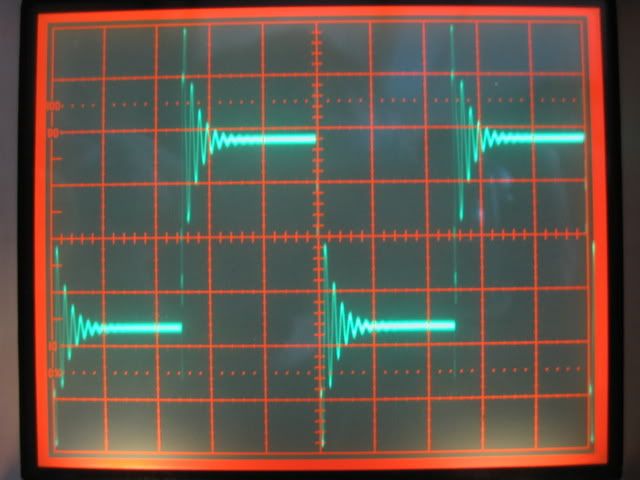
The above photo is the 48 Volt winding of the new transformer when excited by a 10 kHz square wave into the primary. In normal operation the winding is passing sine waves, not square waves, but when the rectifiers turn off the same ringing is excited due to the sudden discontinuation of the current flow.
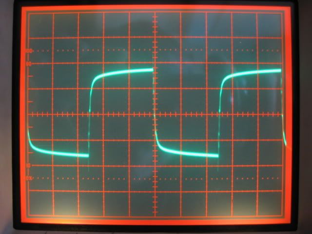
After determining the proper RC network and wiring it across the secondary, the result is pretty dramatic.
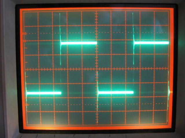
It's a lot harder to see the HF ringing at lower frequencies -- This is 1KHz undamped.
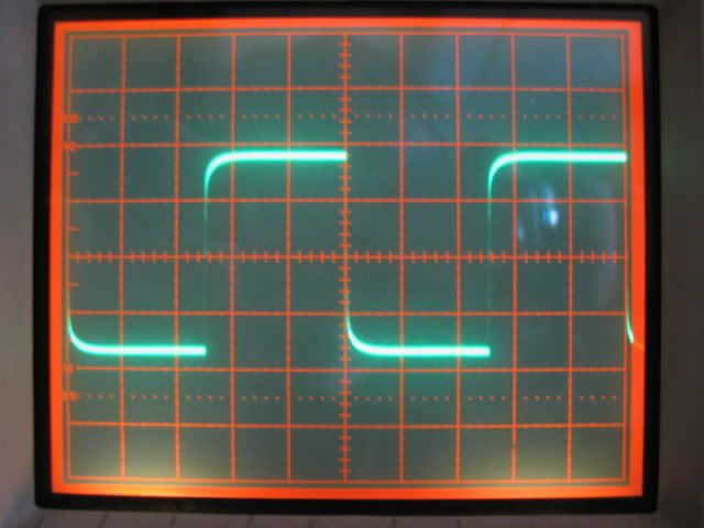
You must look at lower frequencies to check your network, however. Sometimes things look great at 10kHz but lower frequencies have a big peak that was not seen at the higher frequencies. This network works well at all frequencies and is the one that I will add to the Power supply PCB. Interestingly, you really don't have to damp each of the windings individually. By damping the 48 Volt winding, in this case, all the other windings behave as well. The transformer just has to have some way to dump the stored energy and one winding is sufficient to do the job. It makes it a lot less hassle, since the 73 and 84 have three windings and the 81 has four. Damping the 48V winding does it for all of them. I found a nice place for the RC network on the PCB to make it a clean mod. BTW all power transformers need this network. Some power supply manufacturers add capacitors across the diodes and/or capacitors across the secondary with no series resistor. Although this kills the HF ringing, it causes a very large lower frequency resonance to occur. On a commercial power supply I recently modded, there was a 0.33uF cap across the secondary and the result was a 20dB peak at 15kHz. Needless to say, I prefer adding the series resistor. The caps across the rectifiers, by the way are in series with each other and put a similar capacitive load on the transformer secondary, which makes for an unnecessary peak. That's why I use the good rectifiers which require no snubbing, and then I properly damp the power transformer, and all the spurious stuff goes away.
More Later. . .
1. Gain Switch mods:
I modeled the input stage used in the 73 and the 84 in LT Spice to be able to determine the input impedance of the first and second stage. It is not very high, and it changes depending on the gain. That means that the second stage, which has +28dB of fixed gain in Mic mode and +18 dB of fixed gain in Line mode has a different input Z depending on whether it is in mic or line mode. I added much more complete formulas to determine the proper resistors for the gain switch incorporating the input Z. The schematic for the ACMP 81 has another mistake. The load on the line transformer is shown as 6K8 but it is actually 2K2 as in the other schematics and the Neve.
2. Phantom Mods:
The TNC directions instruct you to turn off the phantom power berfore patching a mic. Good advice, but without the 48V switch grounding the filter cap thru the feed resistor, the phantom stays up until externally discharged. It turns out that the ground is not carried through from the phantom power supply to the preamp card. They use a 2 conductor patch cord, but only the +52 is wired. The 48V ground ends at the preamp card. The original 100uF/63V phantom filter cap (soon to be 220uF/63V) is grounded to the chassis by the adjacent screw/pad. I am considering changing that connection and using the 2-conductor cable to return the bottom of the filter. I'm not crazy about using the chassis as a ground wire.
3. New power supply transformer/power supply mods:
I determined the required RC network to properly damp the resonance of the new power transformer. The fast, soft recovery rectifiers that I have added to the power supply do not generate bursts of RF oscillation when they turn off. However, because the transformer is loaded (draws current) only at the peaks of the AC waveform and is unloaded during the transition from positive peak to negative peak, when another rectifier turns on and current is drawn from the transformer winding again. The current from the transformer is drawn in short bursts, and then abruptly stopped.
The stored energy in the transformer causes the ringing. If you add a series RC network across one of the secondaries, the ringing can be almost eliminated, removing one more source of unwanted spurious garbage from the power supply and simultaneously preventing it from negatively affecting the audio. The scope photos are instructive:

The above photo is the 48 Volt winding of the new transformer when excited by a 10 kHz square wave into the primary. In normal operation the winding is passing sine waves, not square waves, but when the rectifiers turn off the same ringing is excited due to the sudden discontinuation of the current flow.

After determining the proper RC network and wiring it across the secondary, the result is pretty dramatic.

It's a lot harder to see the HF ringing at lower frequencies -- This is 1KHz undamped.

You must look at lower frequencies to check your network, however. Sometimes things look great at 10kHz but lower frequencies have a big peak that was not seen at the higher frequencies. This network works well at all frequencies and is the one that I will add to the Power supply PCB. Interestingly, you really don't have to damp each of the windings individually. By damping the 48 Volt winding, in this case, all the other windings behave as well. The transformer just has to have some way to dump the stored energy and one winding is sufficient to do the job. It makes it a lot less hassle, since the 73 and 84 have three windings and the 81 has four. Damping the 48V winding does it for all of them. I found a nice place for the RC network on the PCB to make it a clean mod. BTW all power transformers need this network. Some power supply manufacturers add capacitors across the diodes and/or capacitors across the secondary with no series resistor. Although this kills the HF ringing, it causes a very large lower frequency resonance to occur. On a commercial power supply I recently modded, there was a 0.33uF cap across the secondary and the result was a 20dB peak at 15kHz. Needless to say, I prefer adding the series resistor. The caps across the rectifiers, by the way are in series with each other and put a similar capacitive load on the transformer secondary, which makes for an unnecessary peak. That's why I use the good rectifiers which require no snubbing, and then I properly damp the power transformer, and all the spurious stuff goes away.
More Later. . .


