You are using an out of date browser. It may not display this or other websites correctly.
You should upgrade or use an alternative browser.
You should upgrade or use an alternative browser.
Advice on Peluso p67 mod?(Love the Du67 project! I should have done that!)
- Thread starter achase4u
- Start date
Help Support GroupDIY Audio Forum:
This site may earn a commission from merchant affiliate
links, including eBay, Amazon, and others.
micaddict
Well-known member
****! 
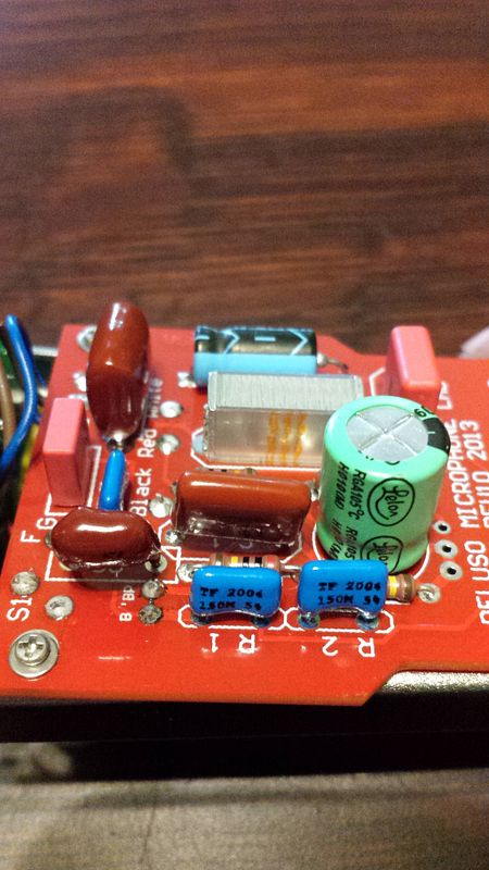
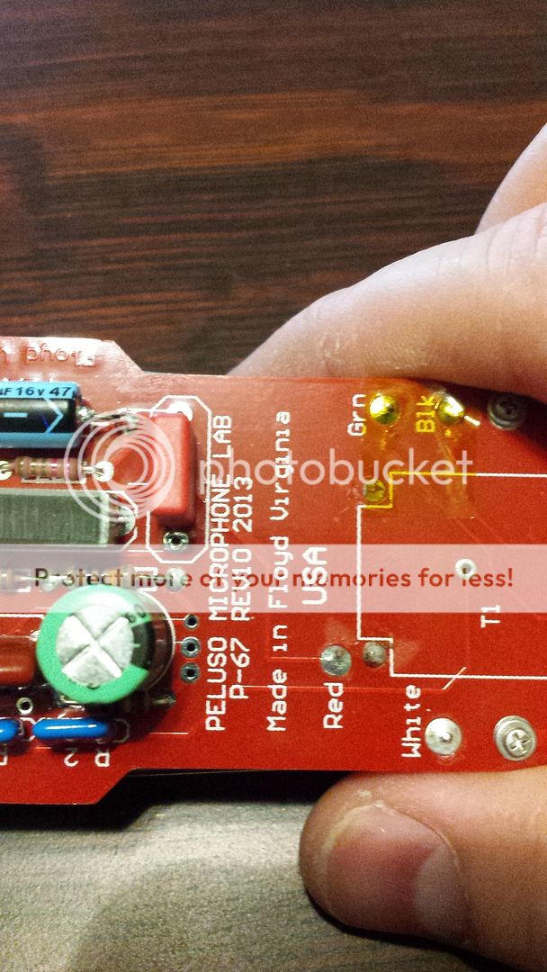
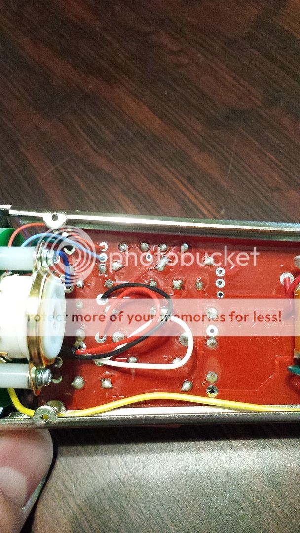
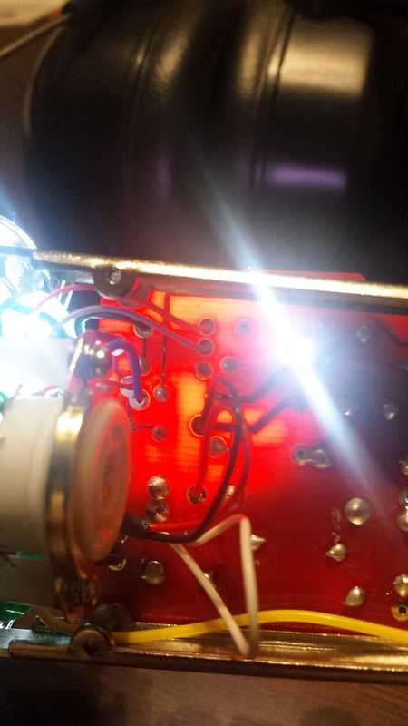
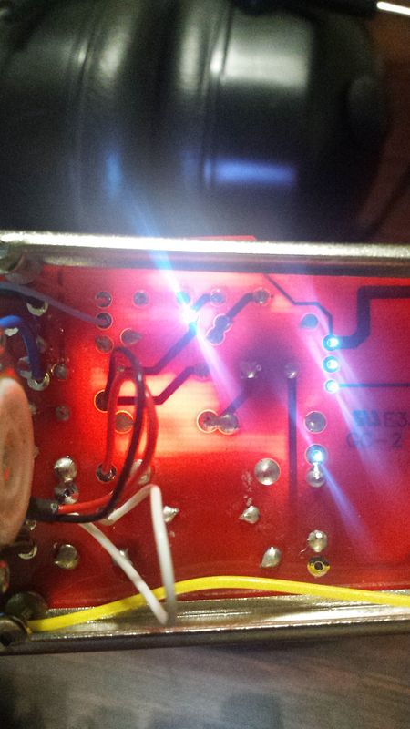
You will need to check where the traces going - i don't see it on the pictures.
Make new pictures (they need to be "sharp" - from the both sides of the PCB (top area with components only).
It need to be centered (not from angles). Put some lamp or flashlight underneath PCB.
Check where is connected (probably tube socket) black wire from the top area of PCB.
Check is it point marked F G is connected to ground
Attachments
Great work! With the light is a lot better 
If you could try to remove pcb would be best.
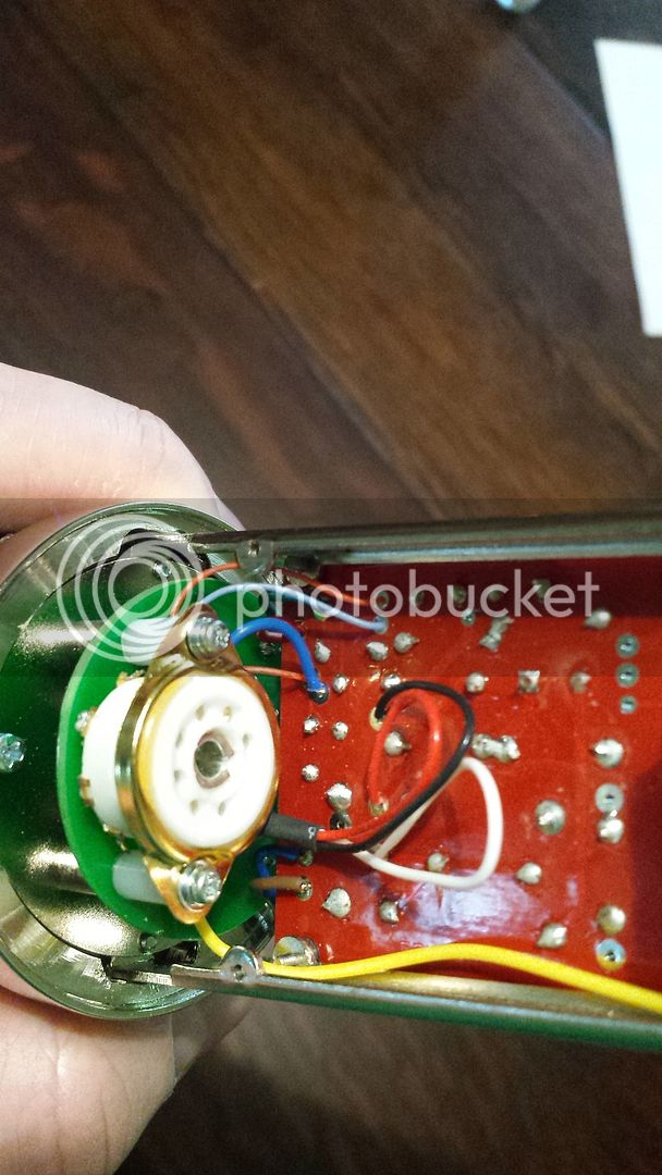
You can also write where goes exactly wires to the tube pins.
If tube is upside down from the left is pin 1. There shouldn't be ground on the tube
Please check also where exactly are connected wires from both switches - which componenets are connected to it on the pcb.
There's still few confusing things, but we are closer than further
ln76d said:Great work! With the light is a lot better
If you could try to remove pcb would be best.
You can also write where goes exactly wires to the tube pins.
If tube is upside down from the left is pin 1. There shouldn't be ground on the tube
Please check also where exactly are connected wires from both switches - which componenets are connected to it on the pcb.
There's still few confusing things, but we are closer than further
Thank you!
Ah ok. So what if I am looking INTO the tube socket itself. No tube installed. Left of the gap is pin 1, right of the gap is pin 7 yes?
achase4u said:Thank you!
Ah ok. So what if I am looking INTO the tube socket itself. No tube installed. Left of the gap is pin 1, right of the gap is pin 7 yes?
Yes. If you are already here, maybe we will finish schematic today?
I am hoping to 
I am bouncing between some work in the shop and this, but I think I can finish the schem info.
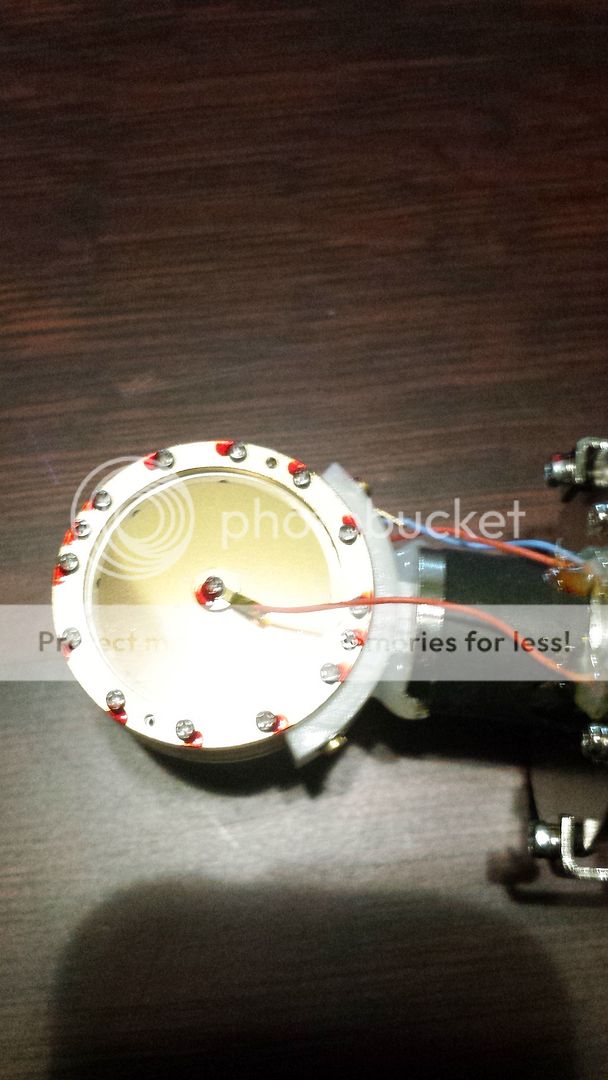
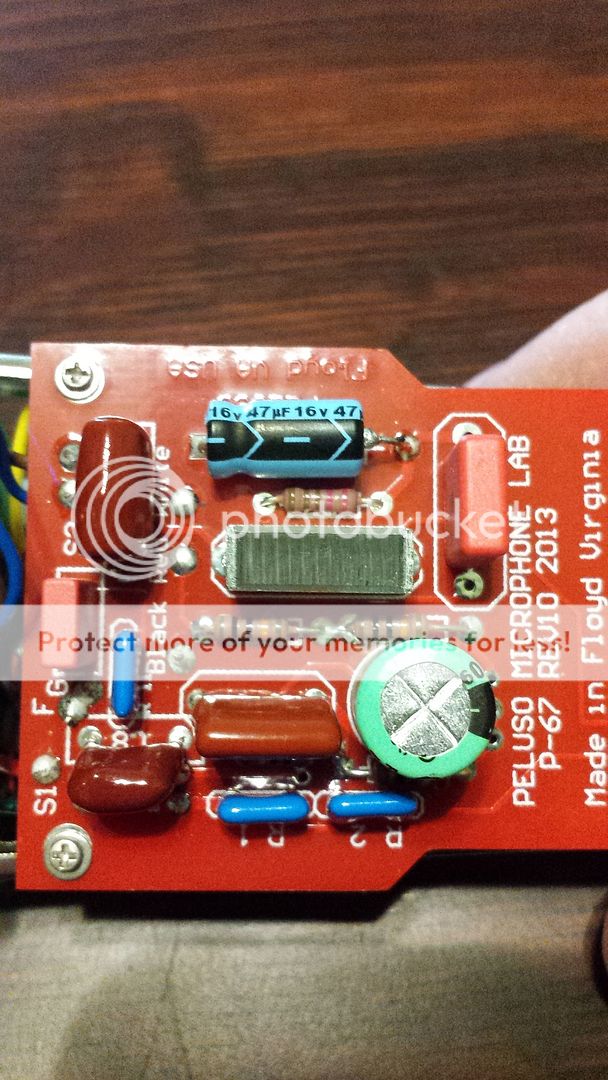
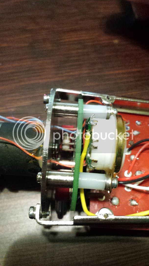
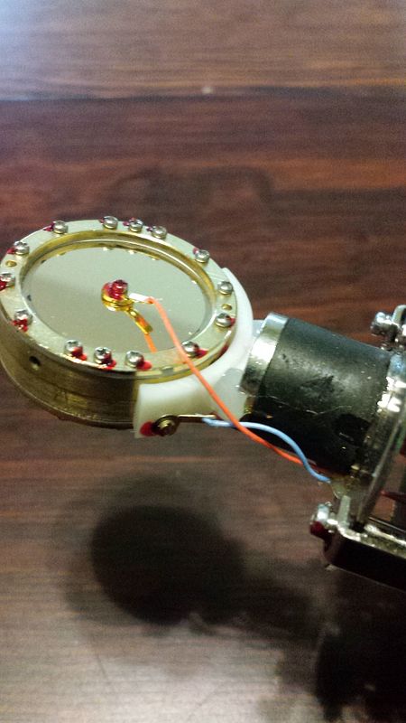
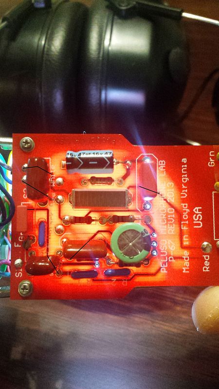
I am looking at the mic now. The hi pass switch is S2. it connects to C7. brown wire to one leg blue to the other. Red and green wire are from switch 1 S1, the pad. The Green wire goes to the back PCB and a trace follows to one leg of C8. The red wire is at S1, which has a trace going to the red wire for capsule front, which is also connected it looks like to a blue wire that goes to tube pin 7. Then the trace continues to one leg of the smaller WIMA red box capacitor, then follows to one leg of R11.
The yellow wire from the bottom mic 7 pin connector goes to tube pin 4.
On the component side of the PCB right under C7, there is marked Black, white and red.
Black goes to tube pin 5
White goes to pin 1 of the tube socket.
Red goes to pin two which is bridged to pin 3.
There is nothing on pin 6.
micaddict
Well-known member
Is John Peluso a member here?
achase4u said:I am hoping to
I am bouncing between some work in the shop and this, but I think I can finish the schem info.
I am looking at the mic now. The hi pass switch is S2. it connects to C7. brown wire to one leg blue to the other. Red and green wire are from switch 1 S1, the pad. The Green wire goes to the back PCB and a trace follows to one leg of C8. The red wire is at S1, which has a trace going to the red wire for capsule front, which is also connected it looks like to a blue wire that goes to tube pin 7. Then the trace continues to one leg of the smaller WIMA red box capacitor, then follows to one leg of R11.
The yellow wire from the bottom mic 7 pin connector goes to tube pin 4.
On the component side of the PCB right under C7, there is marked Black, white and red.
Black goes to tube pin 5
White goes to pin 1 of the tube socket.
Red goes to pin two which is bridged to pin 3.
There is nothing on pin 6.
Drawing
Tube pinout is different way - your 7 is my 1
Doesn't matter
Where are connected both legs of C7 (despite switch)?
How are connecte blue and brown wires to the switch S2?
You can choose center and both side pins
Are you able to check those things and measure voltage in an hour?
Drawing 
Tube pinout is different way - your 7 is my 1
Doesn't matter
Where go other leg of C8?
Where are connected both legs of C7 (despite switch)?
How are connecte blue and brown wires to the switch S2?
You can choose center and both side pins
Are you able to check those things and measure voltage in an hour?
[/quote]
It will be later than that unfortunately I just finished cooking for the family and once that is all done I can look at mic and measure voltage...
Tube pinout is different way - your 7 is my 1
Doesn't matter
Where go other leg of C8?
Where are connected both legs of C7 (despite switch)?
How are connecte blue and brown wires to the switch S2?
You can choose center and both side pins
Are you able to check those things and measure voltage in an hour?
[/quote]
It will be later than that unfortunately
ln76d said:No problem, so leave informaations and tomorrow i will finish it
Here's midnight so i will need to finish few things and go to sleep
Very good! Get some rest and thanks for your help! Ill work on this tonight.
micaddict said:Is John Peluso a member here?
Wish I knew. I figure the mic he made is just how he likes it, so maybe he wouldn't want to advise on mods?
Any manufacturer or designer can't say that his microphone can be better or it's ****** 
Best was Jim Williams which advised mods to his NT2 design and blamed Rode for ****** mike.
Even after mods this microphone is ****** - so sorry Mr Jim


Best was Jim Williams which advised mods to his NT2 design and blamed Rode for ****** mike.
Even after mods this microphone is ****** - so sorry Mr Jim


