Amek Angela Frequency Response

GroupDIY Audio Forum

Help Support GroupDIY Audio Forum:

This site may earn a commission from merchant affiliate links, including eBay, Amazon, and others.

smilan

Well-known member
Joined
May 29, 2017
Messages
502
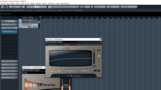
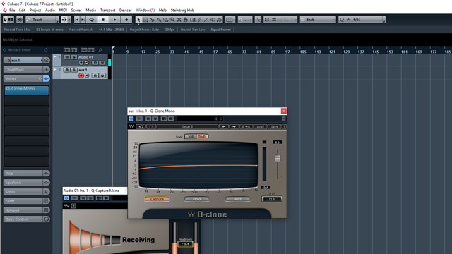
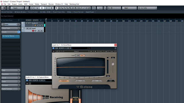
Today I've checked the frequency response of my  Amek Blue Angela at few different outputs using Waves Q Clone and this is what I've found:

Can someone please re do this test on his Angela and see if it acts the same?
Master buss:
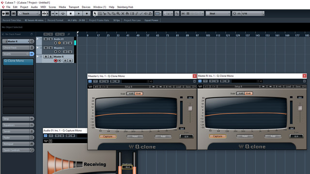
master.jpg

Buss 1:
buss1.jpg

Aux 1:
aux1.jpg

Insert Send:
insert.jpg

I've made this test on few different A10 modules and checked few different Buss Outputs and it acts the same.
I've also never recapd the console so this loss might cause due to old caps?
 
Before making the measurement you shopuld do a lopp back test to make sure your test equipment has a flat response.

Cheers

Ian
 
ruffrecords said:
Before making the measurement you shopuld do a lopp back test to make sure your test equipment has a flat response.

Cheers

Ian
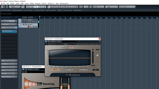
Thanks Ian, the test equipment has a flat response, this is the measurement of line out to line in on my Motu 16a.
out-to-in.jpg
 
I'm recaping a small soundtracs fmx at the moment. I'ts in mint condition, barley used and probably newer than 33 years old. Some of the caps measure under half of its specified value (blue philips caps).
 
OK, looks like the test set up is good. The screen is rather small and the scale is rather coarse so it is hard to see exactly how much drop there is at 20Hz. Any chance of a better pic?

I agree with the advice that a recap is probably in order.

Cheers

Ian
 
ruffrecords said:
OK, looks like the test set up is good. The screen is rather small and the scale is rather coarse so it is hard to see exactly how much drop there is at 20Hz. Any chance of a better pic?

I agree with the advice that a recap is probably in order.

Cheers

Ian
Yes, here's larger images
Buss 1 - 20Hz at -12db
https://ibb.co/3dbxf73
AUX Send -  20Hz at -6db
https://ibb.co/WH4XMZW
Insert Send - 20Hz at -2db
https://ibb.co/khqV5MW
Master Out - 20Hz at -7db
https://ibb.co/CPgN0sf
 
JohnRoberts said:
Do you have a baseline spec?

Maybe recap one module and compare it.

JR

PS and it's spelled 'bus' or should be.
I know someone with the same board that already recaped his console, I'm waiting for him to do the same test before starting recap my board.
 
smilan said:
Yes, here's larger images
Buss 1 - 20Hz at -12db
https://ibb.co/3dbxf73
AUX Send -  20Hz at -6db
https://ibb.co/WH4XMZW
Insert Send - 20Hz at -2db
https://ibb.co/khqV5MW
Master Out - 20Hz at -7db
https://ibb.co/CPgN0sf

Excellent. It is clear from these that the further along you go down the signal path the greater the LF attenuation. Definitely points to needing a recap.

Cheers

Ian
 
ruffrecords said:
Excellent. It is clear from these that the further along you go down the signal path the greater the LF attenuation. Definitely points to needing a recap.

Cheers

Ian
Thanks Ian
 
smilan said:
I know someone with the same board that already recaped his console, I'm waiting for him to do the same test before starting recap my board.

This is an old topic, I advocate using measurements to quantify behavior.

A console is an ideal opportunity to compare near identical (should be identical) audio paths. Make some quick comparisons of individual channels and look for any with unusually weak LF response. Capacitors do not all fail at the same rate, but any bad caps you identify this way, should all be replaced even in the channels that measure OK, since they are likely from the same production batch and should suffer similar aging.

JR
 
I replaced few caps on one of the channels and the LF loss has dramatically decreased.

Before I'm ordering new quality Panasonic low ESR caps I have few questions about increasing the values of the new caps.
I'm intending to double the values of the replace all the coupling capacitors and replace all 100uF/10V  with a 220uF/10V , all 10uF with 22uF, all 47uF with a 100uF .

For the PSU, should I keep the original values of 33,000uf / 40v for the large filter caps?

I don't sure if I need to increase the values of other capacitors which I've marked in turquoise.
* C14, is it a bypass cap for U4? Should I change it's value?
* The three 2.2 caps in the mic preamp (C4, C5 and C6).
* The caps located in the EQ circuit which I don't want to change dramatically (C29, C34, C42).
*The the caps on the Overload Indicator circuit (C69, C70,  C79).
*The values of the +/- power filtering caps (C71, C72, C73, C74).
https://i.ibb.co/1G8k9rm/a10.jpg

* On the A20/A21 module I wasn't sure about C71, C20 and  C33
https://i.ibb.co/ZVBxszP/A21.jpg

On the A32 module:
* Can I increase the values of the following caps:
C4, C40,  C11, C12, C22, C24,  C33, C34, C35,  C36, C50, C52, all the caps at the Power Distribution circuit  (C15, C16, C7, C8,  C9, C10, C57, C58, C73, C20)
https://i.ibb.co/HTW39ps/A32.jpg

 
A10:
Stay with the original values in the overload circuit.

In the PSU section there´s the big 1000uF caps, that´s plenty for that channel. I don´t see a need to increase these.
IIRC the 1uF Tantal is used to decouple the bus amp from the rest of the surrounding circuits. You could use the same value or increase it, but I don´t seen much benefit here. If you don´t want to use tantals then increase the value to 10uF electrolytics. That´s what many chip manufacturers suggest as tantal-replacement in that spot.

A20:
Increase these, too.

A32:
keep C40, C57 original
 
I am not a fan of bigger is always better, especially when second guessing actual design engineers.

Of course if you want to experiment, then experiment... restore one channel to stock values, then modify a second channel with larger values and make comparative measurements.

The data will tell you if bigger is better.

JR

PS: I typically sized DC blocking capacitors for an octave or more below the defining HPF pole, that I tried to do with a film cap in one place. That way the electrolytic caps were effectively never working at audio frequencies, and the LF skirt was well behaved.
 
Looking at the schematic you posted, all the original value caps have a -3dB point of 1Hz or less. Doubling these will make these points 0.5Hz or less. No real advantage to be had by doing this.


Cheers

Ian
 
smilan said:
I replaced few caps on one of the channels and the LF loss has dramatically decreased.

Before I'm ordering new quality Panasonic low ESR caps I have few questions about increasing the values of the new caps.
I'm intending to double the values of the replace all the coupling capacitors and replace all 100uF/10V  with a 220uF/10V , .....
I would go for bipolar/(non polarized) caps with a voltage rating of 25V (or higher) instead.
 
analogguru said:
I would go for bipolar/(non polarized) caps with a voltage rating of 25V (or higher) instead.
I was thinking about bipolar caps, but after looking on the data sheets of the Panasonic 100uF / 25V bipolar caps, I saw it's rated for 2000 working hours comparing to the 5000 - 10,000 hours on the FR series.
https://www.mouser.co.il/datasheet/2/315/ABA0000C1053-947510.pdf

https://www.mouser.co.il/datasheet/2/315/ABA0000C1022-1144690.pdf
 
smilan said:
..... I saw it's rated for 2000 working hours.....
.... at full rated temperature e.g. 85° or 105°.  If you don't run them so hot they will last much longer....

But you can use the caps of your choice and put two of the double value in series (minus to minus) and you will get a bipolar cap of the desired value on the two plus legs.  E.g. If you use two 220uF caps and put them in series as described above you will get a bipolar capacitor with 110uF with the desired lifetime hours.

But if lifetime is so important you could also use 100uF MLCC, they should last forever.  You could also use a combination of electrolytics and MLCC in parallel, values depending on your taste (and money).
 

Latest posts

Back
Top