Ampex PR-10 (354) not working reliably; I'm going in

GroupDIY Audio Forum

Help Support GroupDIY Audio Forum:

This site may earn a commission from merchant affiliate links, including eBay, Amazon, and others.

GrannyGremlin

Active member
Joined
Jul 8, 2024
Messages
28
Location
Toronto, ON, Canada
If you're not in for a bit of a story, you're in the wrong thread. I am feeling loquacious which is probably not the best thing for my first thread since introducing myself, but here we are.

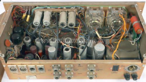
So I have had this late 60s Ampex PR-10-2 preamp for ages. Made some good records with it. Jumped on a second one when I had the chance. But now neither of them are reliable. Put off doing anything because they are such a pain to work on (you'll see in the pics later; very cramped - it's the same circuit as an Ampex 354 but in a chassis 1/2 as big, ostensibly so as to be "portable"). Anyway (local) pro techs don't wanna touch them, they will do the bare min to get them kinda working but they need more love than that. At the time I didn't know enough to work on them, frankly they still kinda scare me, but It's time to put on the big boy pants.

So anyway, this first one I got is a bit of a weirdo in 2 ways:
1) it has no octal sockets for the plug in "input accessories" (so a dummy plug for unbalanced line in, a bridging transformer for balanced line in, or a nuvistor based mic preamp module), and
2) the output stage is based on 6BK7 vs a 6DJ8 tubes as on all the schematics I have ever seen online (I had the original paper docs for this guy including a wonderful centrefold schem, but somehow lost it - I think some tech at some point kept it - honestly can't rememeber).

So when this came to me it was only good for unbalanced line level input. There was a pre-existing mod - an output pad (simple in-line resistor) that was documented on that fold out schematic I lost. As an eager kid I researched the snot out of these, and eventually tracked down a pair of Beyer "peanut" mic input transformers (as used in the plug in preamps) and had them installed, along with 1/4" jacks and a switch (XLR-mic to Beyer tx and 1/4" for the stock line connection), and also put the pad mod on a switch. I had already removed the tape transport control jack and replaced it with a standard IEC power jack (the transport supplied AC to the preamp, on pins 1 - hot, and 2 - neutral, of the 6 or 8 pin connector).

Obviously, even with the mic input transformers stepping up the signal this thing was missing a gain stage so it was not quite enough gain for all situations. Condensors, using an external phantom power supply, and most dynamics were generally fine, but ribbons or something like a Shure SM7b that need an s-tonne of gain, or a quiet source like breathy vocals would require me to daisy chain the channels (mic in to channel A, and channel A out into channel B line in) to get enough gain, which was fine and sounded absolutely divine, just meant I had one less preamp channel to work with if recording live off the floor (and at the time that was a problem).

But then both of my units got the gremlins; I could not rely on them being functional. Took them to various techs and they'd work for a bit and then down again. I had other preamps and left them alone for a few years, figuring they needed a complete overhaul. Eventually, I did bring one unit home (the weirdo described above) thinking I'd get around to seeing what I could do about it. It has been a year or 2 at least.

A very old pic; the rack has seen some turnover and that console is gone (replaced).

preamp rack.jpg

Incidentally the thing labelled Altec was my first attempt at a rack job of some preamp cards/modules (used a PSU kit for the +/-15V and phantom from JLM Audio, added Jensen output transformers which can be used as passive stand alone unbalanced -10 to balanced +4 line level interface when the preamp is off) it's a horrible mess in there (built with all reclaimed wire; I was young OK) but it works. I should use it more, but I digress. ...
 
Last edited:
So yesterday was the day. It takes me a bit, especially when there's all of this [gestures vaguely and erratically all around with both hands] BS going on, to get to things sometimes; I have to get mad about it almost.

Put the MF on the bench, IEC cord into the lightbulb current limiter, phone plugged into the inputs as a signal source, and fired her up.... what, she works fine (gains of the 2 channels don't track very well but sounds great). Huh.

IMG_20240708_1820167.jpg

Notice the Output Selector switches though. Apparently, these sliders have gotten dirty (open frame on the rear) and paradoxically at the same time, loose, so that the upper position (the position I need) is succumbing to gravity and just disconnects, randomly either channel while looking like it is still set to the correct option.

So that's good, but too easy; I know this beast and it plays games, only working when it wants to. I know it's playing nice because it got powered up for the first time in years and is worried it would be tossed in the bin if it didn't pull it's socks up. In any case the channel gains don't match with the gain knobs in identical positions so I have more to do here anyways.

I knew where I had to start: ripping out all the unnecessary tape playback electronics to make space and be able to see what's up in there. This was never gonna go back into service as a recorder (besides the PR-10 tape transports sucked balls apparently - were also built to be "portable").

So here's comparison of my PR-10 to a 354:
IMG_20240708_1820313.jpg

recorder_reproducer_354_2829168.jpg


I had already removed the rec and playback EQ modules when the above pic was taken, or they would be blocking the entire view and prevent me from getting a finger or tool in there, vs the 354 where you could actually change out the tubes without removing those EQ modules. Note also that relay/solenoid on the side with the XLR jacks on my PR-10 vs the octal plug in input accessory sockets on a bracket (with black dummy plugs fitted) on the 354 - all other PR-10-2s I've seen have those sockets.

...
 
Last edited:
I figured the best place to start was with the tape head jacks; follow that wiring (big thick loom) all around and remove the bits as I go. This turned out to be a very good idea.

It also turns out that most of the wiring connections to the main board are those slide on terminals (like the ones for speaker solder tabs, but half - a round female crimp on connector on the wire to a thick pin sticking out of the board). This allowed me to run the unit with playback and pull leads, one at a time, to see if it had any effect or if they were part of the no longer required circuitry.

Trouble started when I followed the loom around the rear, down the side past the relay and got to the switches and calibration panel on the front. Luckily I noticed that the whole front panel was a separate piece from the rest of the chassis and could be removed, or I would have never been able to get in there to unmount the calibration panel and, maybe more importantly, clean the gain pots under the VU meters (hard to turn and scratchy; they needed it).

IMG_20240708_2026463.jpg

IMG_20240708_2026297.jpg

As you can see that is already looking a lot less cluttered (I have the loom from the tape head jacks + the relay + the EQ module panel hanging out of the unit through the crack between the front panel and the chassis side on the bottom right of the pic). At the time of the pic I had already made the first of 2 required soldering tasks/splices per channel. What I am quite sure are cathode bypass caps for the 6AW8s were grounded to a point on one of the rotary switches I had already removed (doesn't seem like the best idea to me, but that's what they did). I sent those to a ground terminal that was formerly used by the leftmost tape head jack - see the 2 little black caps in front of the blue pad toggle switch connected to the yellow and purple wires. I suppose I should shorten those but they were even longer before and it works so moving on for now.

With the front panel down I could remove the calibration panel, which brings me to the only other thing I had to solder during the removal of the reproduce electronics - there are "Rec Cal[ibrate]" trim pots in that panel that control the preamp volume (after the proper gain pots under the VU meters). I have always known these were a liability (cheap trim pots to begin with, and ancient to boot), but no tech I asked back in the day was ever willing to mess with it to bypass them - I had arrived at the point where I had to do it myself.

Turns out it wasn't so hard to figure out (just impossible to do without taking the unit apart as much as I had already, including all the ripping out of unnecessary wiring) and I was able to splice the 2 channel leads from the PCB to the Output Selector switch, with the ones coming back off the Rec Cal trim pots to the PCB. All of these (on the PCB side) were those slip on connectors so dead simple and safe because I could completely remove the harnesses to mod and then put them back. The hardest part was remembering which pins to put them back to but luckily the colour coding of the wires was labeled on the PCB (not totally reliable because colour codes duplicate around the circuit, but if you remember the general area the wire was supposed to go to it was fine) and I took reference pics, which I did not need to reference, but better to be safe.

The good news here is that just bypassing the Rec Cal pots (+ removing unnecessary circuit components, and sliding all those off-board wiring connectors on and off a zillion times effectively cleaning them) had increased the overall gain of the amps by a good 5-10 db.... also the gain pots of both channels were tracking much better now. I was elated.
...
 
Last edited:
I continued and removed the whole tape calibration panel and due to the confidence I had built up so far and getting tired (it was now close to 10pm - I'd been at it since mid afternoon and hadn't eaten anything all day somehow, running on endorphins.... my doc suspects I have ADHD.... seems likely) I got a bit sloppy. Shocked myself twice (because once was not enough to learn my dumb ass apparently) and think I shorted something - Channel A is now again quieter than Channel B at identical gain pot settings. $%&^!

I hope I didn't blow anything other than damaging a tube (I did not see smoke or smell any burning) - the next thing I'm gonna do is swap the tubes between channels to see if that makes Channel B the quieter one. Replacing the tubes is easy and I have some spare 6AW8s (if it's one of the 6BK7s I'ma have to go shopping). If that's not it hopefully there's an obviously burnt resistor that needs changing. We will see, but I'm taking an Archemedes style break and will go back to it in the next few days. I find that helps me because I come back refreshed and without the tunnel vision I may have been trapped in before; see things with new eyes.

Anyway, here's where we're at for now:
IMG_20240708_2230344.jpg

View attachment BeforeAndAfter.jpg

It's hard to tell exactly how much more space there is in there now with the chassis back together (and the bad angle on the After pic) so here is everything I removed (minus the superfluous tubes which I yanked years ago and sold - there were vintage Telefunken and Bugle Boy 12AX7s in there... and I removed 2 of the EQ modules previously as well):


IMG_20240708_2224162.jpg
 
Last edited:
You're most welcome. Thanks for tolerating my info dumping. I get that folks generally like things a bit more succinct around here.


Moving on, I have resolved the channel imbalance issue (it's a dumb one; glad I took that "bath" and came back to it). I didn't blow anything after all.

So I started off by switching the tubes between channels, and even replacing all of them with spares (I did have a stash of 6BK7s after all; nice surprise). That didn't do it, but in the process of doing that I did notice that I have been saying/thinking V1 is 6AN8 when it is really a 6AW8 (as per the schem). Sorry about the confusion - I am dyslexic and the names are a mere 1 char difference AND I love noval triode-pentodes which these both are (I have a lot of gear that uses both of these tube types, from phase splitters to reverb drivers or in tremelo and fuzz circuits). I have corrected the posts above.

So once I established it wasn't the tubes, I started looking at the wiring to the tubes, especially where I did the splices to bypass removed components. I found the problem and then remembered what happened (please recall I was unfed and fatigued by this point, while also tweaked on excitement) - after I had relocated the ground connection for the 6AW8 cathode bypass caps I was poking around while doing something else and accidentally yanked out one of the leads (the purple one). In my haste to continue my current train of thought I put it back but in the wrong place - there was another pin right next to the correct one. I moved the purple lead back to the correct pin and now the channel gains match (the VU meters are a tad off, and one cannot expect logarithmic taper carbon track pots to track well with each other, but the LED meter on the mixer I have plugged into the outputs confirms things are equal vs 7 +/-1 db out of whack as I was seeing before).

Looks like I'm done with this one! Time to put it back in the rack at the studio, give it a quick test with a pair of identical microphones, and bring the other unit home for it's turn on the bench.
 
Last edited:
So I learned a few things about this circuit that I didn't realise before - just never had cause to study the schems quite as closely as I have this week or poked around as deep into the physical units. Here's some notes and thoughts about the PR-10:

High level signal flow (for stand alone preamp use):
input jack > input accessory socket (missing in my case - replaced with switchable mic input transformers) > gain knob ("Record Level" more of a pre V1 input trim) > triode half of the 6AW8 > Rec Cal trim pot (now removed) > Output Select switch (now removed) > monitor amp (both halves of the 6BK7 or 6DJ8) > Transformer > VU meter > output jack

Metering:
The outputs are taken right off the VU meter, which come right after the OT. While from a technical implementation perspective this makes sense, it is not the best place to measure (from an input recording to tape perspective) because it includes all the gain from the output/monitor amp section, therefore not giving the user an accurate sense of signal level to tape (though it does make more sense for signal coming back off tape because ostensibly you are going through the monitor amp out to a mixer or power amp and speakers - recording to tape seems the more critical application here as regards metering e.g. to maximise S/N etc). This is however, better for my use case, since the monitor amp is in play if taking the output of the unit to a DAW.

The Calibration Panel:
The Rec[ord] Cal[ibrate] trimpots are counter-intuitively not what one would think. From the moniker one would assume that it is a master volume trimmer before hitting tape, but in reality it is completely removed from, and parallel to the tape head driving part of the unit. You probably don't want a cheap trimpot between source and tape anyway.

After the 6AW8 triode input stage, the signal splits to both the Rec Cal trim pot, and to the recording EQ modules (and related switch) which go on to feed the tape head drive circuitry. The Rec Cal is pretty much an input stage master volume with no other purpose than to trim the signal feeding the monitor amp. I always had this pot dimed so it made sense to remove it. The Rep[roduce] Level trim pot makes a bit more obvious sense as it controls the signal level coming back off tape (after a 12AX7 and the reproduce EQ modules) before the monitor amp (and there is no other gain or volume pot in play in that signal path).

Phone Outputs and The Monitor Amp:
The headphone jacks (on either side of the gain knobs) come right off the primary side of the output transformers, or depending on how you want to look at it, right off the second half of the 6BK7 (or 6DJ8) which is a cathode follower, no doubt to buffer the monitor amp (1st half of the 6BK7) from the varying load of up to 2 pairs of headphones (more if you use splitters) and a transformer balanced line output. I was surprised at this, but it works great. By the by, this thing is also a pretty sweet tube headphone amp, if a bit large and heavy (slightly less so now ;P). For mic input the headphones may not be loud enough for direct monitoring in a loud environment (e.g. live off the floor recording; generally fine for overdubbing because less extraneous noise), but still useful for checking tone and drive levels before recording and well enough volume for listening back to line level signals.

The Schematics and PR-10-1 vs PR-10-2:
There are 2 scehmatics currently floating around the net (including here) and they are not labelled properly.

If you see the schem as a single image file for the entire unit, it is likely a low res version of the PR-10-1 schem. Ignore that one and look for the version that is 2 files, left and right sides of the schem. This is for the single channel version of the PR-10 which has 1 major difference compared to the 2 channel version: it has separate mic and line inputs. Since the power supply is the same they had extra capacity ( and space in the chassis) to put a proper 12AX7 based mic preamp in the unit (vs having to use a plug in nuvistor-based module). The line input retains the input accessory socket, so you could put a preamp module in there and mix 2 mics to the half track tape head or the single line out (mic and line inputs have separate gain pots).

Then there's the schems for the PR-10-2, the 2 channel version which are also split into 2 files except the first is the Record half of the circuit and the second is the Reproduce half (and power supply). Neither is labelled as such in the file itself, most often not in the filename either (unless you get it from me). I have not been able to find a good quality version of the Record schem - all the ones I have found are super lo rez and hard to read. The reproduce schem is better but still not great. These are useful just for high level reference and seeing how things are connected between the 2 channels (i.e. the dual stereo headphone out jacks vs single mono headphone out on the single channel model). For all other purposes, especially checking component values, it is best to reference the PR-10-1 schematic (and keep in mind what the differences are; luckily it is mostly just the dual input thing and the headphone out).

Output/Monitor Amp tubes:
I am not sure how common it is to have 6BK7s in the output section vs the 6DJ8s as in the schematics (all versions I have seen online). I do not recall offhand what is in my other PR-10 (at the studio so can't check right now; I have some notes from the last time I bought tubes that make me suspect 6DJ8 but will have to confirm), but I am curious about this - which is more common to see in there and when did they switch?

The 6DJ8 is the successor tube to the 6BK7 and probably the more desirable/more hifi of the 2 (also current production exists so cheaper) but despite the same pinout they are not direct replacements for each other (nobody subbed in the 6BK7 for what was originally a 6DJ8 from factory; also the tube types are printed on the main board next to the tube sockets - definately not a mod). Technically the 6BK7 has a bit more gain (mu of 40 vs 33; plate dissipation of 2.7 vs 1.8 watts according to their respective data sheets) so I guess I'm fine with that being what I have here.
 
Got the second unit home. It is the more problematic of the 2 units.

This one has the input accessory sockets with nuvistor based mic preamps installed. I had forgotten that I had already modded it a bit with TRS I/O parallel off the XLRs, removed the tape head jacks and EQ modules, but not the calibration panel and all the switches. Those preamp modules are part of the reliability issues - I have replaced the nuvistors in there multiple times (should still have some spares).

So the plan is:
1) test with mic input (expect issues from what I recall of the last time I tried). Quite sure the channel B meter will just peg at max as soon as I turn this thing on too (it's not in the pic because I knocked on it a few times until it settled to rest position).
2) remove the mic modules and set aside; jumper the octal sockets (or make quickie DIY dummy plugs) so I can test the rest of the unit without the input accessories using unbalanced line input
3) However that goes I need to rip out the rest of the record electronics like I did with the first unit (as well as the TRS I/O - it's a liability at this point and I don't need it since this unit lives on a patchbay and I only ever use it for mic signals). If not working, I will have to proceed to check the tubes/voltages (luckily the schem provides voltages coming in to the tubes), contacts of all the slip on connectors/general cleaning, and possibly a do a cap job - looks like all original caps in there vs my other unit that has newer electros (and even had one pair of electros replaced with massive orange drops - you can see them clearly in the pics above in front of the XLR I/O and peanut transformers).
4) have a look at the mic modules. I also wonder how easy it would be to repurpose the 2 unused 12AX7 sockets (for the playback amp) to build in a PR-10-1 style mic preamp so I can ditch the plug in modules altogether. I will compare the schems when I get to this point and decide if that is viable/worth the trouble vs fixing the modules. I would have to get some mic to grid transformers, and not Beyer peanuts this time (I have no idea what the PR-10-1 used; may not have been Beyers like in the plug in modules and schem does not say). Otherwise I would consider modding the mic modules to solid state (I have a schem somewhere for a discrete transistor version used in later years, and with the AG440 IIRC, utilizing the same Beyer transformer - should have all the needed parts for that on hand). That should be more reliable (but less desirable option).
5) see what I can do about the dent in the lower left rack ear and the pegged Ch B meter

IMG_20240718_1157306.jpg

IMG_20240718_1159325.jpg


Some questions I have:

- So how the F do you test a nuvistor to see if it's good? Can you even or is it a matter of swapping out and if that fixes the issue the tube was the problem after all?

- I have read that pegged meters could be due to being dirty (it is very dirty in there) or the front glass being pushed in just enough to hinder movement back to rest (vs when the signal actuates the coil); the fact that I could return it to rest by rapping on it seems to track with that. Any advise on dealing with it? I've never dealt with a wonky meter before (aside from replacing one on my Orban comp - apparently I got the last spare part form Orban, and this was over a decade ago so don't bother calling; they are also all out of optional output transformers by the way) . I don't suppose replacement of the meter is an option - would be hard to find the same part and it is crammed in there so alts may not fit.
 
So I expected this thing to not be working at all - because that is what I remember from when last trying to use it, so mic plugged and power and... Channel A works fine. Sounds great even.

Channel B, however, is nada (not even noise/hum/static). That explains the "no go..." on the masking tape on that preamp module vs blank tape on the other one.

Now the first thought was to swap the modules between channels because that would prove if the modules are the problem, but then it occurred to me that if I do that and there's something wrong with Ch B I could damage the other module. Also the problem could be the other tubes or those slip on connections.

It is probably safer to check the voltages on the sockets first (the module schem I have very handily shows voltages at the pins and throughout the circuit). But before even that I think I will remove both modules, jumper the sockets for unbalanced line input, and test again to make sure it is indeed the Ch B input accessory that is dead. No matter the result of that I may as well get all the superfluous wiring out like I did on the other unit, because that needs to be done anyway. Then (assuming Ch B works with the line input or after having resolved any issue there), check voltages at the octal sockets and the components inside the Ch B input accessory module.

By the by, I noticed an interesting behaviour when testing Ch B - I had the back open (it's on a hinge in case that wasn't clear in the pics of the other unit above) and as I was checking the XLR connections when I had no signal I brought it back up to closed position and it kinda bonked into place on the central chassis. This caused the Ch B needle to move a tad and get stuck at like -10 (a light rap with a knuckle zeroed it out again) and both channel record lights came on (momentarily).... the record lights should not be working at all. We'll see if that keeps happening after I remove the unused wiring (and my TRS I/O mod) - there's some looms bunching up on the rear right of the chassis when the back door is closed which could be the cause.
 
So I tried making a dummy plug (FYI romex is just too small to jumper an octal socket, but it is exactly the right size to fit in the pins of the male plug, i.e. a tube base) but no signal. Double checked I jumperred the correct pins. Frick.

While I was frustrated about that I got to removing more superfluous wiring.... and it hit me - these things are Pin 3 hot (I am using RCA to XLR adapters that send tip to Pin 2 and ground to 1 - nothing on 3).

Anyway can't retest that now because I'm balls deep clearing out the unnecessary wiring loom. I just noticed that (unlike the 1st unit) this has some extra wires in that loom that I need to keep: purple and white for the heater rail to the accessory socket, but also a red wire that I assume is B+ but it doesn't go direct to the socket so I gotta trace that to be sure.

Now I gotta take apart the loom to free those 3 leads I need and figure out where to plug them back in (slip on connectors) because I went ahead (looking at a pic of the first unit) and unplugged everything along the rear edge of the PCB. Luckily between the cable length and the pics I took before of this unit I got the general location of where those go; the colour coding on the PCB should home me in from there. I can confirm by pulling all the tubes and checking the voltages at the accessory sockets, and I will test those before I put the wires back too just to confirm that is what those leads are for.

The loom passes underneath the input accessory socket bracket, so I unmounted that to see the bottom. Yep - you can see the red, purple and white wires I"m talking about coming out of the loom and up to a turret board on the bottom of the bracket (red) and direct to the octal sockets (purple and white).

White and Violet Heater and Red B+ wires in loom.jpg

Is it odd that these power rails were bundled in a loom with signal cable? Like for tidiness should I put them back in the loom or leave them out (and shorten them - they are much longer than they need to be)? Incidentally the heater wires were twisted together outside the loom but not within it.

Those brown caps probably need to be replaced. Looks like these are a final B+ filter (4uF 450V) before that hits pin 7. They just put stuff all over the dang place.

Starting a parts shopping list.
 
Confirmed - the red wire is the B+... and the MF goes to the relay before doubling back to the board. Not looked at where it's twin (going off to the right in the pic above) is doing just yet.

There's going to be a lot more soldering/rerouting things on this one to remove all the tape head/record electronics... though the cathode bypass caps I rerouted on the 1st unit do not seem to exist here for some reason.
 
OK good progress here.

Rewired my DIY dummy plugs for pin2=hot and mounted them. Left the heater and B+ leads to the octal sockets disconnected just in case I messed that up (I don't want to blow my fone - quite sure 290V to the headphone jack would do that). Aaaaaaaaaand we have working stereo headphone amp - both channels work, so I have confirmed that the ChB mic preamp module is the problem.

Working Dummy Plugs.jpg

MetersAlive.jpg

As you can see the gains of both channels are not tracking very well - hoping bypassing the Rec Cal trim pots will resolve that like it did on the first unit, but super glad to report that the ChB meter is not pegging or sticking or whathaveyou - so once I fix the mic input module that should not be an issue anymore.

I have also proved that the B+ wire coming off the accessory socket turret strip to the safe switch is not required for the rest of the amp to work because that was disconnected. The pin on the PCB was the supply (just over 300V) vs the supply coming the other way off the switch (that makes sense but so many weird things in here so wanted to be sure). Also checked it with that (unnecessary from the switch) red wire connected directly to the PCB pin in case that was doing something and no it isn't - no change in gain/tone with that connected or yanked.

Now I can proceed with wiring removal, being able to double check that any given wire is not required.

It feels as if the volume on the headphone jack is lower than expected (vs my other unit). I may have to add those missing cathode resistor bypass caps to see if that gives me more gain. Also, will have to check if the "output pad" mod on my first unit was adding a resistor or bypassing one. I always have that set to off on my other unit so could easily lift the same resistor for more gain if that's what was going on vs adding, but I doubt that is the case. I seem to vaguely recall a resistor was drawn in on the original schem; if so then it's a weird mod to increase the gain (cathode bypass) and decrease it with a pad (it was fixed, on all the time, when I got the unit - the tech I took it to years ago to install the Beyer input transformers put the switch for that in because he saw it on the schem I supplied to him). Otherwise the other unit was much better maintained (a lot of caps were replaced, and replaced with quality parts, like Sprague orange drops in 2 spots - this second unit has what appears to be all the original caps (which I suspect may be an issue).
 
All superfluous wiring has been removed. Again, there is about 7db more gain and the channel levels track better after the Rec Cal trim pots were removed.

The wiring on the XLR (actually older than that - Cannon) jacks looks like it has been messed with. Can't tell if you can see that in the pics above but it was not looking good, so redid all that - setting Pin 2 as hot while I was at it. This unit will only have XLR/Cannon I/O so it matters vs the other unit which has separate TS 1/4" jacks. This way if I ever plug something unbalanced into there it will still work.

Rewired the dummy plugs back to schem specs (vs my rewire to compensate for Pin3=hot) fired her up again and after a scare (forgot to plug a slip-on ground connection back in - oscilation.... then plugged it in the wrong PCB pin - the current limiter bulb lit up ... 3rd time was the charm).

You can see the twisted purple/white heater wires and the red B+ (both along the rear of the PCB) are back in place.

IMG_20240721_2023434.jpg

IMG_20240721_2024263.jpg

Now have to figure out the ChB preamp module issue and decide how much of a cap job this thing is gonna get (and which caps are even in circuit anymore).

I did check the voltages at the octal accessory sockets (no preamp plugged in so unloaded):

B+ to Plate is 290V (schem says should be 150) - even unloaded that seems high.
Heaters are getting 11.2V (vs 12.6) - and that is with the heater rail not as loaded as it should be (2 12AX7s and a 12BH7 were pulled years ago due to not being needed for preamp use).

I guess we'll see what that looks like after checking/changing some caps and voltage dropping resistors. It's all carbon comps in here and they've probably drifted in the last 60 years.
 
Last edited:
Dammit - I just noticed that the preamp modules are not the ones I have the schem for (part# 96440-01 - 40db preamp) but rather the successor model (96440-03 - 45db preamp).

96440-02 (60 db preamp) and 96440-04 (45-60db switchable preamp) are also compatible units but from what I recall they changed the pinout when they switched to solid state (part# a few digits longer and starts with a 4).

Can't find the schem for the 03s I have. May have to do this the hard way.
 
OK well that wasn't so bad.

Ampex 96440-03 45db Mic Pre Module.png
compared to the 96440-01 schem I already had:

Ampex 96440-01 40db Mic Pre Module.png
Note the changes around the cathode and deletion of the heater resistor. Confirmed both my modules are the same (the labelling on the Beyer peanut transformer varies - stamp vs sticker) as do the wire colours (or there is some overspray of green on the good one - solder flux residue or something, I dunno, but it looks like other colours poke though at different points along the wires - can't really tell in the pics,. but under a good light IRL).

IMG_20240722_1613079.jpg
IMG_20240722_1613220.jpg
IMG_20240722_1613377.jpg
IMG_20240722_1613522.jpg


The one on the right (with "G" on the transformer) is the bad one.

I thought I figured out what was wrong with the bad module because I got "OL" on my meter on every resistor I tried to measure (some of them are isolated enough that they should test accurately in circuit), but then I had the same issue on the 'good' module. I was able to measure the 0.22uF cap (0.218uF) on the good one (can't reach the cathode on the bad one with the probe) and check continuity (e.g. between pins 1 and 2 etc) so that is puzzling - perhaps things are just very dirty in there.

Anyway, not sure how I would change those out anyway - especially that 270k - I can't get an iron in there. There's a screw in the bottom of the socket key - I tried taking it out but that does not release the assembly from the shield skirt - didn't want to use too much force as these things feel so delicate. That 270k to ground is right down in there under the Tx (see pic below) - no way to get at it.

IMG_20240722_1614514.jpg

Further, I do not know for certain that the original tubes in these modules were in fact 6DS4s - that's just what's in there now (and IIRC a tech told me he changed at least one of them out to fix it when I took it in years ago). What I do know is that they are not equivalent to 7586 (e.g. hi vs med mu) but the circuits are so similar it seems that in this case they may both work if not provide the same amount of gain.

7586 (CV9686) - Medium mu triode. (mu = 35)
=
6DV4 - Medium mu triode, consumer version of the 7586 usually gold plated (mu=35)

6DS4 - High mu triode, extended cutoff (mu = 63)
= (? - data sheets not super close but all the online tube stores sell them as equivalents)
6CW4 - High mu triode, consumer version of the 7895, the most commonly seen (mu=65)

Nuvistor data sheets if anyone cares: Tube Datasheets - Dr.Tube

Anyway 6DS4s are available at most of the usual tube stores for about US$16 ea so that's not too bad.

The spares I have are in fact 7586. ... I would try subbing them in if I knew for sure these spares were good (maybe they were the ones that were removed as dead from these modules years ago) because it would prove the point that the tube is the issue. I don't even want to switch 6DS4s between modules because the bad module could blow the good nuvistor. .... I could test my 'spares' in the good module first I suppose - that should be safe, right?
 
I paid this dude online C$20 for his collection of Ampex PR-10 docs. So now I have readable schems (multiple covering various eras of production) but the gold may be the 40 pages of Service Bulletins. A lot of them are irrelevant (about the tape transports) but there is some good stuff, like increasing the preamp gain by 6db with a simple resistor change, and decreasing preamp distortion with another resistor change; still going through it all and making notes.

Then there's a few LOLs. Remember how part of my reliability issue was the output select switches? There was a bulletin for that; they changed the part.

Ampex LOL.jpg
 
Ah here we go: The output amp tube was changed from 6BK7 to 6DJ8 for all units serial number > 5200 in Aug 1964, so both of my units are older than that. I do not have the serial numbers (it was probably on the case or the transport section which I do not have).

They had kits you could order for conversion. I have no problem with that tube (and a small inventory of spares) so I ain't gonna bother, but now I can edit a schem with the correct values around that tube.

.... though it does involve replacing the selenium rectifier diodes from the filament supply with standard silicone (1N400x series would do - they used 1N607 which is only 0.8A vs 1 like a 4001). That would be a bit of a PIA but might be worth it without the tube change (involves upping some resistors and moving the connections of those huge 2F filter caps... huh and apparently that really was a 2F and a 1F - so my one unit has the originals still , they must have changed 2 both 2F later).

Anyway, I'll stop play by playing this now. Just excited to have proper documentation.
 
Last edited:
That was about the end of the relevant service bulletins; the only remaining one was, and here's another LOL, recommending to replace the 1n607 filament rectifiers (which were already replacing the original Se rectifiers in a previous bulletin) with 1n4385, because, and get this, they were seeing (or expecting) failures due to the current handling ability of the 607.

The bulletins are confusing because the diagrams included are labeled "old" and "new" which I take to mean before and after, but what they really show is the PR-101 vs 2. Additionally, the PR-10-1 power supply has post mod part values but still shows the Se diodes. Anyway, that page was a bad quality so I am showing the filament supplies from the higher quality schems I now have - PR-10-1/"Old" top and PR-10-2/"New" bottom.

Filament Supply Schems.jpg

Then there's this bit circled in orange below:
PR-10 Power Supply.jpg

I pulled both the 12AX7s years ago so I need to deal with that ground connection off V5 somehow. Note: A and B (or X and Y) go to the preamp module for the nuvistor fillaments. I haven't dealt with a DC filament supply before, nevermind a pseudo split supply that isn't using a center ground line; guitar amps mostly use AC straight off a 6V secondary.

I suppose it would be best and easiest to just put a tube back in the v5 socket (could be old/dead as long as the filaments are OK). That way it is closer to the full load, and avoids ugly pcb/tube socket jumpering. Well the best would be a complete redesign of the fillament supply but as that will likely be very messy with regards to PCB hacking, it's a non-starting proposition.
 
Was out of town for a few weeks so this was on hold but getting back to it now; have had time to think through what to do next and work on a parts shopping list.

*note all part numbers are Channel A/Channel B

Regarding the filament power supply:
Both units appear to have the original Se diodes. I don't think I am going to mess with this because it's working. I will replace the filter caps on the one unit with the originals still in, the other one (no nuvistors) has more modern Sprague replacements (orange plastic shell vs cardboard) so will leave them alone for now. I will also plug in some dead 12AX7s into the currently empty V5 sockets just to make the ground connection (as per the orange circled portion of the power supply description in the post above this one). It's just so much cleaner and easier than jumpering pins 4 and 5 to 9 (would probably have to use resistors vs plain wire and I don't wanna play around to figure that out).

Preamp gain mod (as per Ampex Tech Bulletins):
I have confirmed that both units have the original 1M R7/R8 (off the 6AW8 triode which is the first gain stage after the inputs and input accessories), so will up them to 1.8M as recommended for an easy +6db. The labels for those on the PCB looked closer to a 750k resistor (adjacent to R7/8) so I was very confused for a sec, so boo Ampex for the screen print design. No idea what those 750ks are for (no other label nearby) but while I was poking around there I decided that I should replace C2/3 (cheap ceramic discs; have probably drifted a lot and not temp stable even when new - it gets hot in there) ... which led to the following bit.

Deletion of unnecessary caps (and replacing a critical one):
So replacing C2/3 ceramics with film caps will be tight because there are some other caps very close, but checking the schem I have confirmed that all the other caps around the 6AW8 can be removed because they are all serving the unused pentode half of the 6AW8. It occurred to me that that this may cause instability in the tube, but since I have already removed the record selector switch, the pentode half is no longer getting any B+ so it should be fine (see diagram below - red circles are parts to be deleted, green are to be replaced). I have confirmed that by measurement - the triode plate is getting 2xxV and the pentode plate kinda fluctuates between 1.x and 2.x V which is just leakage from other parts of the circuit.

Removing C1b and c has another additional benefit - it allows for easier replacement of C1a (not on the diagram; further to the left from where I cropped it) because I can just get a single cap vs trying to find a multi-cap can that will fit. This is important because C1a is filtering B+ to the input accessories (both sockets - channels A and B), so considering my problem with burning though nuvistors, replacing it seems like a good idea as it is currently the original 60 y/o part in both units. Same for a few other caps I identified earlier (also not shown in the schem snippet below) which are attached directly to the octal sockets vs on the PCB (which is what the snippet below shows). IIRC those were filtering the filament supply to the nuvistors.

6AW8 part changes (R=del G=replace).jpg
 

Latest posts

Back
Top