


Hi,
I was checking the AMZ Mosfet Booster circuit from jack Orman and have some questions that would like to ask you guys out.
The circuit can be found here:
http://www.muzique.com/schem/mosfet.htm
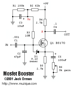
As the output is taken from the "Drain" of the Mosfet isn't this output signal Polarity reversed ("Phase Inverted") when compared to the input signal?
Doesn't it form an "Inverted" buffer?
Is there any reason for taking the output from the "Drain" instead of from the "Source"?
If the output is taken from the Source of the Mosfet it seems to me it would be "Non-Inverted" so would respect the same Polarity that is presented at the input?
Any reason for this, or am I'm missing something here?
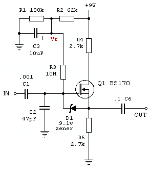
Would the below example of the Non-Inverting work?
Thank you so much for all your help
I was checking the AMZ Mosfet Booster circuit from jack Orman and have some questions that would like to ask you guys out.
The circuit can be found here:
http://www.muzique.com/schem/mosfet.htm
As the output is taken from the "Drain" of the Mosfet isn't this output signal Polarity reversed ("Phase Inverted") when compared to the input signal?
Doesn't it form an "Inverted" buffer?
Is there any reason for taking the output from the "Drain" instead of from the "Source"?
If the output is taken from the Source of the Mosfet it seems to me it would be "Non-Inverted" so would respect the same Polarity that is presented at the input?
Any reason for this, or am I'm missing something here?
Would the below example of the Non-Inverting work?
Thank you so much for all your help
Last edited:

