Theory, Practice and Sexlife of the "Reflected Plate Amplifier" Hybrid, low Voltage Tube circuit

GroupDIY Audio Forum

Help Support GroupDIY Audio Forum:

This site may earn a commission from merchant affiliate links, including eBay, Amazon, and others.

thor.zmt

Well-known member
Joined
Feb 3, 2020
Messages
776
Location
South East Asia (not China or SAR's)
Folks,

Elsewhere in a different thread, the subject of the RPA came up. I think it is interesting form DIY, as it allows DIY'ers to make essentially very tubey tube circuits, that run on relatively low voltages (e.g. 24...48V), do not necessarily run the tubes in starved anode condition (but can) and can be powered if necessary from very low voltage power supplies.

I am sure some will argue that it does not give "true tube sound", but in my experience that depends on specific implementation. I'd like this thread to be specifically about the Theory, not about asking feedback on attempt's to make it work.

Originally the RPA was at least popularised, promoted and patented by Aphex. The Patent is expired and I would argue that the patent had no validity due to obviousness. Still, interesting in many ways.
Some so-called "high perveance" Tubes can operate very well at 48V. There is a white paper by Apex on a suitable circuit, mind you, I'd not use a 12AT7 in this circuit myself, but ECC88 or similar.

IMG_20230415_050527.jpg


From here (link):

Aphex Tubessence White Paper

I have seen an earlier circuit from Aphex (IIRC) that used just a TO220 PNP Bipolar transistor and the tube heater as ballast for the transistor.

Like so (Aphex Patent):

IMG_20230415_051600.jpg


I thought this circuit very interesting but never got around to trying the precise setup, but I have designed products around variations and refinements of "Tubessence" which were well received. I am attaching a commercial but discontinued design of mine, that is a "perfected" RPA. It was actually actually was quite liked by some studio people. Especially in the final mastering step.

Several 1,000 were made and sold and it's reliable. A review that describes the function is here:

iFi iTube Review

The "FX" is a version of Phaedrus "FRANCINSTIEN" (plus some extra) and the Taddeo "Digital Antidote II" respectively.

I apologise for the way it is drawn, which does not make the circuit easily to understand, I thought I had a file from TINA, but alas no. This schematic is for PCB design and the full product.

1681728671939.png

Here is a photo of the actual PCB:

1681728610740.png

You can see it is quite SMD part heavy.

The current through the tube is equal to the bias of the 2N4403 (MMBT4403 is the SMD version), so the tube operates in "starved anode" mode (~ 24V/0.1mA). Big advantage, extremely long life and ton's of harmonics. The second "advantage" was not one for "HiFI" use and the later version dropped HD a lot and used a much higher anode voltage and current.

The Mosfet can be replaced by IRF710 or similar without other change. Design center is 3V Vth which equates to 4mA in the 2N4403. The Mosfet follower at the output runs at ~10mA so max output into 600 Ohm is only 4.2V (+14dBU)

The follow-up version made a number of other changes. The PNP Transistor was replaced by a P-Channel Mosfet, the positive supply was raised to 48V from 24V, the current source NPN was replaced with Mosfet and most crucially a DC servo was added to eliminate the output capacitor and also the capacitors in the feedback loop. It is also a lot more complex and not really suited to DIY.

Should anyone wish to produce a commercial product based on this, I suggest to contact me for the updated version and other changes and naturally a licencing agreement. I can also help apply the same principle to other products (e.g. Microphone Pre etc.).

The circuit posted here is completely depreciated and outdated and not recommend for mass production, but it is suitable for DIY assembly, once the SMD parts are replaced by TH parts.
I would still roll in some of the updates I applied to the later version and rearrange the feedback loop to include the coupling Cap and feedback DC blocking Cap.

Thor
 

Attachments

  • itube 1.pdf
    547.5 KB · Views: 5
Ok, tube mother lubbers, let's talk a bit how this puppy works. This module assumes basic under standing of the "transresistance" mode of the transistor operation and of tube operation.

Remedials available via WIkipedia, RCA Tube Manual and RDH and Horowitz & Hill. Peruse them.

Here the basic circuit again, from the Aphex Patent:

1682071105520.png
Let's figure out operation. The tube Aphex uses is 12AT7 and compatible, it would not be my choice.

Datasheet here:

https://frank.pocnet.net/sheets/093/1/12AT7.pdf

For the PNP Transistor let us assume MJE350, datasheet here:

https://www.st.com/resource/en/datasheet/mje340.pdf

We have a 15V positive rail given.

I consider this rather low, I would prefer ~50V which we need anyway for the Phantom power if we use a Mic. A MC33063A can be used to make +55V @ ~ 0.25A from a 12V DC Source, using standard boost topology followed by a charge pump.

An inverting Buck-Boost can make -18V and a Boost converter can make +18V, so we get +/-18V + 55V regulated DC from 12V (~ 3A or more) using DIY friendly parts (low switching speed, DIP cases available).

I'm not covering this here, if someone is interested, start a new thread and I'll chime in as time allows.

Back to RPA, we have +15V, the BE junction of our PNP drops 0.7V, so the tube anode voltage is ~ 14.3V minus any bias. Bias is going to be negligible, so the tube will operate near zero bias. This means grid emission may be substantial and hence C101 & R101 are used, to block DC both ways.

Let's start backwards with the operating point.

R102 & R103 form a Feedback Divider for negative feedback. They work at both DC & AC.

R104 is the load for the output Transistor. Let's assume the transistor passes ~ 50mA and the output voltage for DC is ~ 1V.

So R104 = 13.6V / 50mA = 270 Ohm. Power rating 13.6V * 50mA = 0.68W, so use 2/3W Metal film or better 5W.

Looking at the MJE350 datasheet, at 50mA I eyeball the current gain as ~ 80, so 50mA collector current requires ~ 0.625mA base current. This is the Anode current for the 12AT7. With the datasheet curves and 14.3V/0.625mA we get ~ 50mV Bias:

1682073324929.png

Thus R102 ~ 0.05V / 0.625mA = 82R.
We have a feedback network, to get a gain of (say) 10 / 20dB we need a resistor R103 to be 9 * 82 = 750 Ohm. As we have a finite loop gain, we need to tweak the 750 Ohm value a bit, for a "eyeballed" value let's make it 910 Ohm.

The DC output voltage becomes the Cathode voltage multiplied by feedback divider, so (0.05V * (910/82))+0.05V = 0.6...V

Thusly:

+V = 15V
-V = 12.6V
R101 = 100k/0.25W
C101 = 1uF/63V/DC/MKP

R102 = 82R/0.25W
R103 = 910R/0.25W
R104 = 270R 2W or higher power

Tube Va ~ 14.3V
Tube Vk ~ 0.05V
Vout (DC) ~ 0.6V

Obviously, the output needs a coupling capacitor.

Now, what is our open loop gain?

The tube transconductance I "eyeball" at 4mA/V. There is a large margin of error at these very low voltages.

The transistor adds a gain of 80, so at the transistor collector we see around 320mA/V transconductance.
With 270 Ohm load resistance (ignoring external load and feedback divider) we get 0.24A/V * 270R = 86 so our feedback in this stage is ~ 18dB (8) for 20dB closed loop gain, not a lot.

Our output impedance is 270 Ohm divided by the feedback factor so appx. 270 / 8 = 33 Ohm.

In reality we should include the feedback resistors, but they both lower OLG and output Impedance, it's friday evening just before beer o'clock and let's keep life simple.

This is an extremely simple circuit for a low voltage Tube stage and will have a strong "tube" type harmonic and sonic signature.

In my view, while likely great as an effect, like for example makeup gain after a passive summing mixer to add "glue" to the mix or with a circuit optimised for more gain and 2 stages as a "colourful" Microphone Preamp, I would not build this circuit as presented here..

We can do better and get a lot more control over parameters, but in order to improve the basic RPA, we need to understand it first. I hope this can help to understand this circuit a little better, before we look at improvements.

Thor
 
Last edited:
Thanks for posting Thor. Not quite ready to get stuck into this but looking forward to when I do. I expect I’ll have some questions one I’m done trying to digest this post.
 
Last edited:
Very good and through explanation - I really appreciate work like this. Thanks!

BUT: Have you actually listened to how these circuits sounds, even with good tubes and careful design? Methinks there was this very good reason why Aphex never really made it in industry, apart from their "aural exiter" that has also fallen out of fashion now..

/Jakob E.
 
Very good and through explanation - I really appreciate work like this. Thanks!

Thanks. I will expand from here.

This thread is sparked by discussions in another thread where someone mentioned he was scared by the high voltages tubes need.

I gave some examples of how this is not true and eventually badly wrong (technically speaking) schematics of attempts at this circuit showed up and others complained that it was all OT, so I created this thread.

BUT: Have you actually listened to how these circuits sounds, even with good tubes and careful design?

You read the thread from the initial post?

A stand alone "tube buffer" using a variant of this circuit (with many improvements and/or changes) was produced (across three Marks) and sold well enough to totally exhaust a big warehouse lot of over 30,000 pcs GE 5670.

Methinks there was this very good reason why Aphex never really made it in industry, apart from their "aural exiter" that has also fallen out of fashion now.

I still use the Aural Exciter in every club Setup I do. Set "just so" the results are excellent.

I had one big and famous club (in Peking, at workers stadium) where a "know-it-all" knew "Aural Exciter = Bad" and removed it from the chain.

A few weeks later I get a call that the system sounds bad. I come, flying in from Hong Kong, look, get them pull the "Goode olde Aphex" from storage and put it back. And all was well again.

The commercial succees of a product or brand in a market is, in my experience, largely unrelated to product quality.

In fact I claim the modestly named "Thors second corollary to Sir Thomas Gresham's law".

Gresham’s law is an economic principle that states “bad money drives out good money.”

Thor's second corollary states "Bad cheaply priced equipment drives out (of the market) good fairly priced equipment."

I gave my assessment of the sonic merits (or lack thereof) at the end, like so:

"This is an extremely simple circuit for a low voltage Tube stage and will have a strong "tube" type harmonic and sonic signature.

In my view, while likely great as an effect, like for example makeup gain after a passive summing mixer to add "glue" to the mix or with a circuit optimised for more gain and 2 stages as a "colourful" Microphone Preamp, I would not build this circuit as presented here."

It's also a touch of "too much Aphex" just saturation dialed up a trifle much.

Much of my work on this circuit went into reducing the almost comical and stereotypical "Toob Zound" that reminded a lot of a ca Y2K Hong Kong audiophile tube setup, such as you see in "Infernal Affairs":


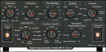
I preferred always "less tooby" but also added a (in the final mark) a "Tubeyness" control, making the device close to the one and only Kotchka Inc Audio Demoronisator AD-1:

Model_AD1.gif

Anyway, I think this circuit is worth spending time on and being low voltage, it is very diy friendly.

Thor
 
Last edited:
A Mu-Follower digression

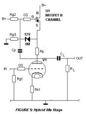
Let's take a break from the RPA and look at another "low voltage" capable circuit. It is commonly used with conventional high voltage HT, but doesn't have to. It is the Hybrid Mu-Follower:

1682751464985.png

Q1, Rp & Cp from an AC current source and DC follower that largely fixes the anode voltage of V1.

Rs1 is optional and can be used to draw extra current through the Mosfet Q1, it could also be replaced with a solid state CCS.

V1 is biased by Rk1 in a conventional manner, Grid Stopper GS and Gate Leak resistor Rg1 are also conventional.
CL is a conventional output capacitor and RL is the load. Taking the output from Mosfet Source gives us a very low output impedance, much lower than conventional tube stages.

If a given stage does not need to drive a low(ish) impedance load the output can be taken from the tube anode in a conventional manner:

1682778399919.png

A note on safe voltages...

"The International Electrotechnical Commission (IEC) has adopted standard voltage values that are considered sufficiently safe.

Extra-low voltage (ELV) is defined as not exceeding the relevant voltage limit of 50 V AC RMS and 120 V DC. In a dry skin condition, this extra-low voltage can be assumed safe to touch, for an indefinite period of time."


So if we keep +B below 120V it is reasonably safe to DIY.

Commonly we do not need a lot of output by "tube standards". If we can support appx +20dBU we should be good.
For that I suggest appx 20V across the Mosfet Q1.

The Mosfet Q1 should have low input and reverse transfer capacitance. A IRF710 will have ~ 170pF Cin which is bootstrapped by the Mosfet's follower action and 6.3pF reverse transfer capacitance.

Using IRF710 we have around 3V Vgs Threshold Voltage.

The Mosfet will have very high transconductance in the region of 100mA/V at 10mA and thus has around 10 Ohm source impedance. If we use a Rp of ~ 100 times of Rs, so 1kOhm the effective anode load for V1 will be in the order of 100kOhm in parallel with around 8pF capacitance.

Allowing 5V for Rp & 20V means if we have a +B derived from ~ 40V AC (ELV) via a doubler (means we get < 120V DC - again ELV) and allowing for 10% mains overvoltage and 10V for a IRF710 based capacitor multiplier filter for +B leaves us 100V +B and a Anode voltage for V1 that is ~ 75V.

So we get as practical example:

+B = 100V
Q1 = IRF710
GS = 100 Ohm 0.25W
Rs1 = 7k5 Ohm 2W
Rg2 = 3M3 Ohm 0.25W
Rg3 = 16M Ohm 0.25W
CL >= 2.2u 100V
RL = 100k Ohm
V1 = (see text)
Rp = (see text, depends on tube)
Rk1= (see text, depends on tube)

Now let's pick V1. We can have up to 5mA @ 75V.

12AX7 and 12AU7 are common in Pro Audio, I would consider 5670/2C51/6N3 instead, as well as ECC88. But let's look up 12AX7 & 12AU7.

12AX7 first:

1682781341665.png
We see that with 75V (red line - sorry, it's 80V, not a big difference here) we have a decent Operating Point at ~ 0.85mA (green line) and -0.5V Bias.

With 5V for Rp, we get Rp = 5V/0.85mA = 5k6 Ohm.

With 0.5V for Rk1 we get Rk1 = 0.5V/0.85mA = 560 Ohm.

The effective anode load will be ~ 560k Ohm (blue line) so gain will be ~ 80V/V if Rk is bypassed with a suitable capacitor as commonly applied.

12AU7 next:

1682781958202.png
We see that with 75V (red line - sorry, it's 80V, not a big difference here) we have a decent Operating Point at ~ 5mA (green line) and -2V Bias.

With 5V for Rp, we get Rp = 5V/5mA = 1k Ohm.

With 2V for Rk1 we get Rk1 = 2V/5mA =390 Ohm.

The effective anode load will be ~ 100k Ohm (blue line) so gain will be ~ 17.5V/V if Rk is bypassed with a suitable capacitor as commonly applied.

Other tubes, use the same method to calculate.

So we can see that we get a fairly normally operating Tube circuits that can be run with Safe Extra Low Voltage power supplies, which in turn can be made from off the shelf low voltage parts.

Multiple stages can be combined just like any conventional circuit, for circuits like microphone Preamplifiers etc..

Thor
 
Last edited:
A Mu-Follower digression

Let's take a break from the RPA and look at another "low voltage" capable circuit. It is commonly used with conventional high voltage HT, but doesn't have to. It is the Hybrid Mu-Follower:

View attachment 108436

Q1, Rp & Cp from an AC current source and DC follower that largely fixes the anode voltage of V1.

Rs1 is optional and can be used to draw extra current through the Mosfet Q1, it could also be replaced with a solid state CCS.

V1 is biased by Rk1 in a conventional manner, Grid Stopper GS and Gate Leak resistor Rg1 are also conventional.
CL is a conventional output capacitor and RL is the load. Taking the output from Mosfet Source gives us a very low output impedance, much lower than conventional tube stages.

If a given stage does not need to drive a low(ish) impedance load the output can be taken from the tube anode in a conventional manner:

View attachment 108440

A note on safe voltages...

"The International Electrotechnical Commission (IEC) has adopted standard voltage values that are considered sufficiently safe.

Extra-low voltage (ELV) is defined as not exceeding the relevant voltage limit of 50 V AC RMS and 120 V DC. In a dry skin condition, this extra-low voltage can be assumed safe to touch, for an indefinite period of time."

So if we keep +B below 120V it is reasonably safe to DIY.

Commonly we do not need a lot of output by "tube standards". If we can support appx +20dBU we should be good.
For that I suggest appx 20V across the Mosfet Q1.

The Mosfet Q1 should have low input and reverse transfer capacitance. A IRF710 will have ~ 170pF Cin which is bootstrapped by the Mosfet's follower action and 6.3pF reverse transfer capacitance.

Using IRF710 we have around 3V Vgs Threshold Voltage.

The Mosfet will have very high transconductance in the region of 100mA/V at 10mA and thus has around 10 Ohm source impedance. If we use a Rp of ~ 100 times of Rs, so 1kOhm the effective anode load for V1 will be in the order of 100kOhm in parallel with around 8pF capacitance.

Allowing 5V for Rp & 20V means if we have a +B derived from ~ 40V AC (ELV) via a doubler (means we get < 120V DC - again ELV) and allowing for 10% mains overvoltage and 10V for a IRF710 based capacitor multiplier filter for +B leaves us 100V +B and a Anode voltage for V1 that is ~ 75V.

So we get as practical example:

+B = 100V
Q1 = IRF710
GS = 100 Ohm 0.25W
Rs1 = 7k5 Ohm 2W
Rg2 = 3M3 Ohm 0.25W
Rg3 = 16M Ohm 0.25W
CL >= 2.2u 100V
RL = 100k Ohm
V1 = (see text)
Rp = (see text, depends on tube)
Rk1= (see text, depends on tube)

Now let's pick V1. We can have up to 5mA @ 75V.

12AX7 and 12AU7 are common in Pro Audio, I would consider 5670/2C51/6N3 instead, as well as ECC88. But let's look up 12AX7 & 12AU7.

12AX7 first:

View attachment 108443
We see that with 75V (red line - sorry, it's 80V, not a big difference here) we have a decent Operating Point at ~ 0.85mA (green line) and -0.5V Bias.

With 5V for Rp, we get Rp = 5V/0.85mA = 5k6 Ohm.

With 0.5V for Rk1 we get Rk1 = 0.5V/0.85mA = 560 Ohm.

The effective anode load will be ~ 560k Ohm (blue line) so gain will be ~ 80V/V if Rk is bypassed with a suitable capacitor as commonly applied.

12AU7 next:

View attachment 108444
We see that with 75V (red line - sorry, it's 80V, not a big difference here) we have a decent Operating Point at ~ 5mA (green line) and -2V Bias.

With 5V for Rp, we get Rp = 5V/5mA = 1k Ohm.

With 2V for Rk1 we get Rk1 = 2V/5mA =390 Ohm.

The effective anode load will be ~ 100k Ohm (blue line) so gain will be ~ 17.5V/V if Rk is bypassed with a suitable capacitor as commonly applied.

Other tubes, use the same method to calculate.

So we can see that we get a fairly normally operating Tube circuits that can be run with Safe Extra Low Voltage power supplies, which in turn can be made from off the shelf low voltage parts.

Multiple stages can be combined just like any conventional circuit, for circuits like microphone Preamplifiers etc..

Thor

Perfect timing, something to get stuck into over the long weekend, thanks Thor
 
I definitely wouldn't consider 120V DC safe in any "sufficient" way - I really don't understand where they get this figure from?

Around here, safe part of the LVD was traditionally specified with a cutoff at 48VDC - which is why phantom power and telephones are supplied such..

/Jakob E.
Who got slammed quite hard by +118V recently
 
The current CE definition of Safety Extra Low Voltage is 50VAC.120VDC. Note that 50VAC is 141Vpp.

However, the relevant standards for electrical safety are changing to a hazard based approach rather than a 'you must meet or exceed these measurements' approach. This may change things significantly.

Cheers

ian
 
I definitely wouldn't consider 120V DC safe in any "sufficient" way - I really don't understand where they get this figure from?

"The International Electrotechnical Commission (IEC) has adopted standard voltage values that are considered sufficiently safe.

Extra-low voltage (ELV) is defined as not exceeding the relevant voltage limit of 50 V AC RMS and 120 V DC. In a dry skin condition, this extra-low voltage can be assumed safe to touch, for an indefinite period of time."


This is the basis for the Building Site use of 110V electrical tools, together with a 230V -> 50V-0-50V isolation transformer with the center tap earthed.

As Ian notes, all standards fall under Panta Rhei.

Voltage is actually inconsequential, it's the current. Some people conduct better than others.

Being stressed out from fear over high voltage will make skin wet. I frequently get mildly zapped on 230V AC (I often work on powered circuits against all rules) and tend to be quite cavalier about it, with some minimal precautions. Seems I am a poor conductor.

Thor
 
I definitely wouldn't consider 120V DC safe in any "sufficient" way - I really don't understand where they get this figure from?

Around here, safe part of the LVD was traditionally specified with a cutoff at 48VDC - which is why phantom power and telephones are supplied such..

/Jakob E.
Who got slammed quite hard by +118V recently

I forget the exact values but from what I’ve read, I believe 120VDC comes from the idea that with the average resistance a human body presents (I think this was said to be around 2kohm?), it would take about 120 volts for a lethal amount of current to flow through you.

Although you make a good point that maybe ‘just less than enough to kill you’, doesn’t equate to everyone’s idea of ‘safe’ 😅
 
Its all relative...
I've work on 11000V systems regularly and its much safer than mains 230V due to all the safety protocols in place.
I've been shocked by 1000VDC on a Insulation tester and it wasnt too bad, better than coffee to wake you up in morning...
 
The police in my town in South Africa used to apply 1000V on wind up meggers to the nutsack of the unfortunate uncooperative individuals who they had in custody all the time and they were fine...not sure about the reproductive abilities afterwards...
 
The police in my town in South Africa used to apply 1000V on wind up meggers to the nutsack of the unfortunate uncooperative individuals who they had in custody all the time and they were fine...not sure about the reproductive abilities afterwards...

That sort of game is not limited to South Africa. Again, voltage as such is immaterial, the current flowing does damage. A Megger has very limited current.

FWIW, static electricity is commonly >> 5kV and just mildly painful, if at all. The reason is that current is miniscule.

Thor
 
I feel like we need to be a bit careful here. I’m sure this won’t apply to anyone here but I’m afraid someone with poor knowledge on electrical safety will misinterpret what’s being said here as high voltage = inherently safe.

If the circuit you’re interacting with has the potential to provide enough current to be harmful then the voltage absolutely is a factor in deciding how safe it is.
 
I feel like we need to be a bit careful here. I’m sure this won’t apply to anyone here but I’m afraid someone with poor knowledge on electrical safety will misinterpret what’s being said here as high voltage = inherently safe.

Hmm, maybe such a person needs to win a Darwin award?

If the circuit you’re interacting with has the potential to provide enough current to be harmful then the voltage absolutely is a factor in deciding how safe it is.

Yes and no. Dry skin makes things safe that are lethal with wet skin. The precise current path also matters. It's a surprisingly complex topic. Also completely OT for this thread.

Thor
 
Last edited:

Latest posts

Back
Top