etheory
Well-known member
Hi there!
I am starting this thread to share my experience with DIY'ing a 2500/225L-inspired compressor.
I am working with a schematic I found on this board, that if you really go looking, is pretty easy to find.
I started off this crazy journey with this thread on DIY CNC'ing a 2520 I simulated in LTSpice based on information that I again picked up off this board ( and was not hard to find ): http://www.groupdiy.com/index.php?topic=46998.msg590345#msg590345
There are some basic examples of tests on that DOA at the end of that thread.
Next up, I've taken the schematic and broken it into 3 parts, 1.) The input stage, 2.) The VCA and sidechain circuitry and 3.) The output stage.
Today I verified 1.) and 3.) Next I will work on 2.)
I wanted to share some images of the input and output stage tests.
First here is the input stage, which is a relatively simple, almost text-book, electronic de-balancing circuit based on my 2520 ( in the original it's a 2510, but I haven't built my 2510 yet ):
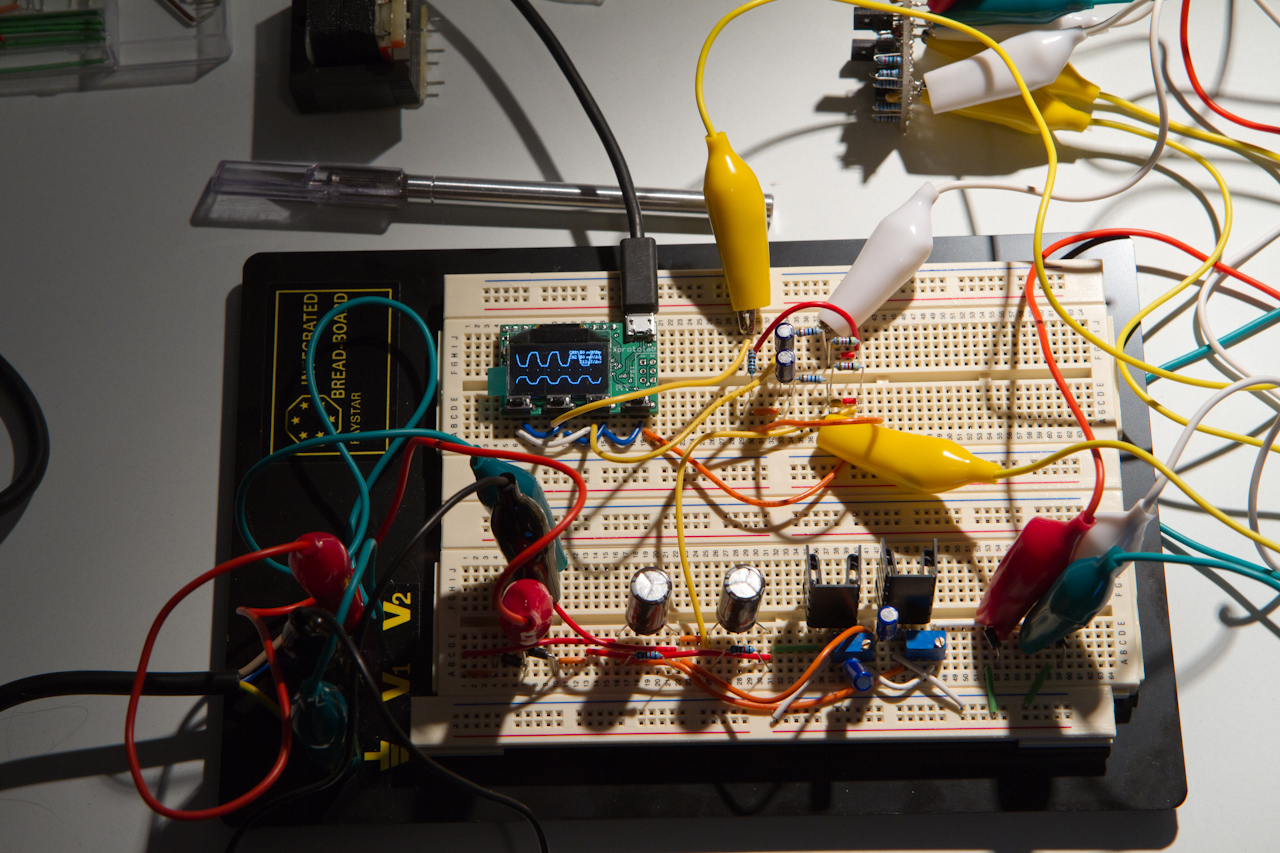
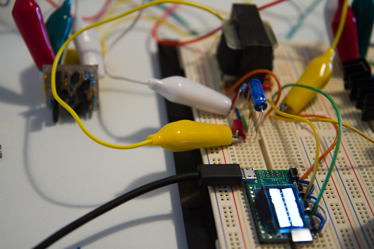
You can see the Xprotolab in there also assisting me in testing. The top trace is the input, and the bottom trace is the output. You can clearly see that this is an inverting stage with gain 0.5x when run unbalanced ( as here, since one side is grounded, when I input a proper balanced signal it'll be 1x ).
Next up I tested the output stage:
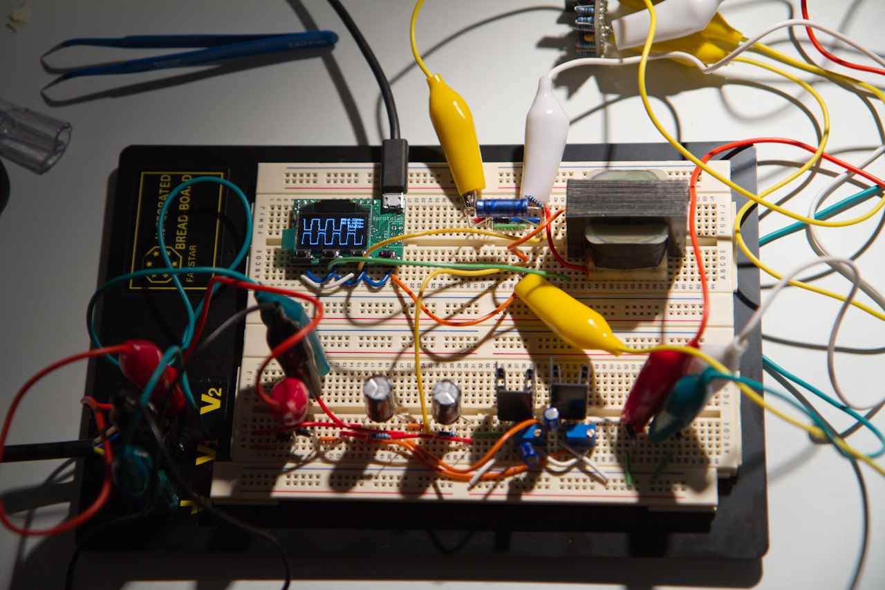
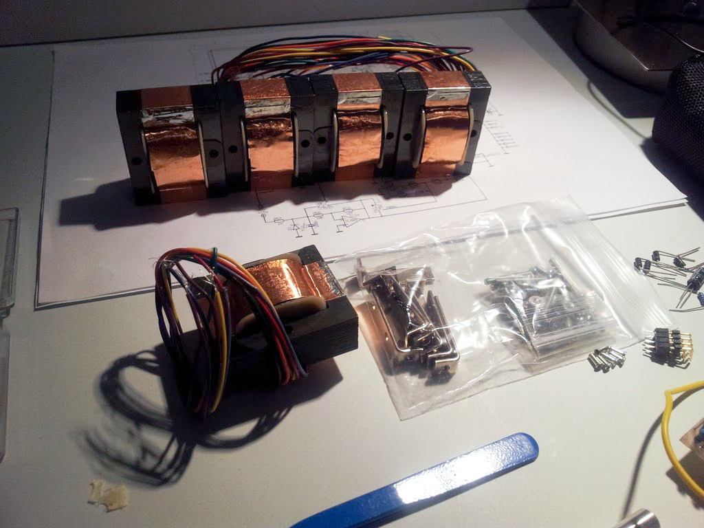
Here you can see the gorgeous Ed Anderson classicapi.com 2623-4 (http://classicapi.com/catalog/product_info.php?products_id=31) output transformer. This will soon be replaced by a 2503 once it arrives - although throughout development I will be testing the sound of both, since I want this to be a character compressor as much as a partial 225L replica. You can also see the rather nice Vishay output cap and WIMA bypass cap.
Here you can see that this stage is also inverting, and this time of gain 1x
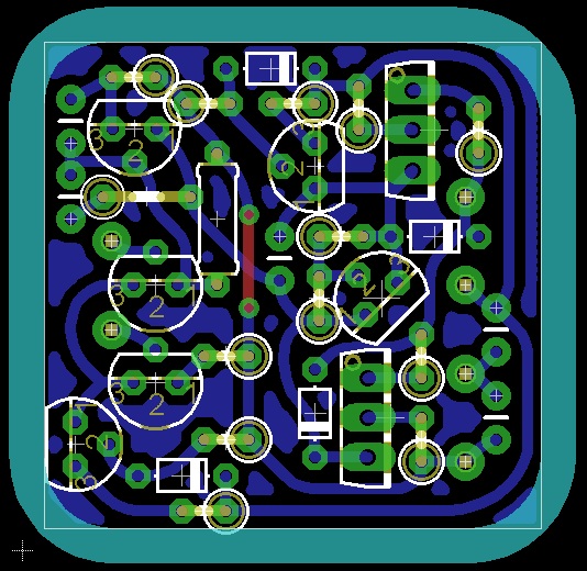
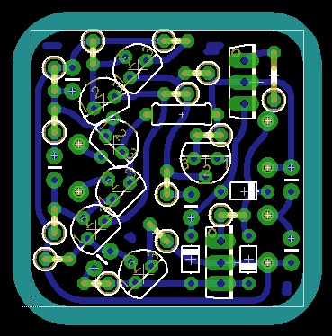
Next step is to finish my Eagle board for my take on the 2510 after much tweaking on LTSpice, again entirely based on information found on this board, which I'm going to make in 2520 footprint since it allows for the most options for future expansion ( i.e. I'd love to design some other DOAs and put them in this to see how they sound too.... )
After that, which I hope to all have finished by the start of next week, is the significantly more complex VCA stage, which I'll breadboard up in stages and test also.
I think that the input, VCA and output stages will all go on one PCB just like the actual 225L, and then I can dev the sidechain and control voltages on another, which will aid both development, and simplify the interfacing at this stage. I'm not sure if I'll combine them in the final version onto one PCB or not. Since I'm building 4 of these in one box, that might end up the best option.
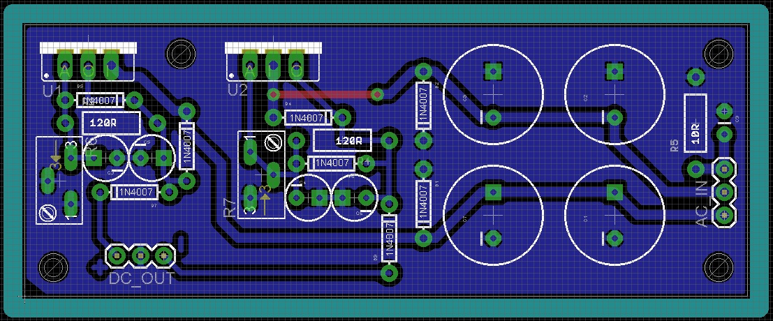
Some more images:
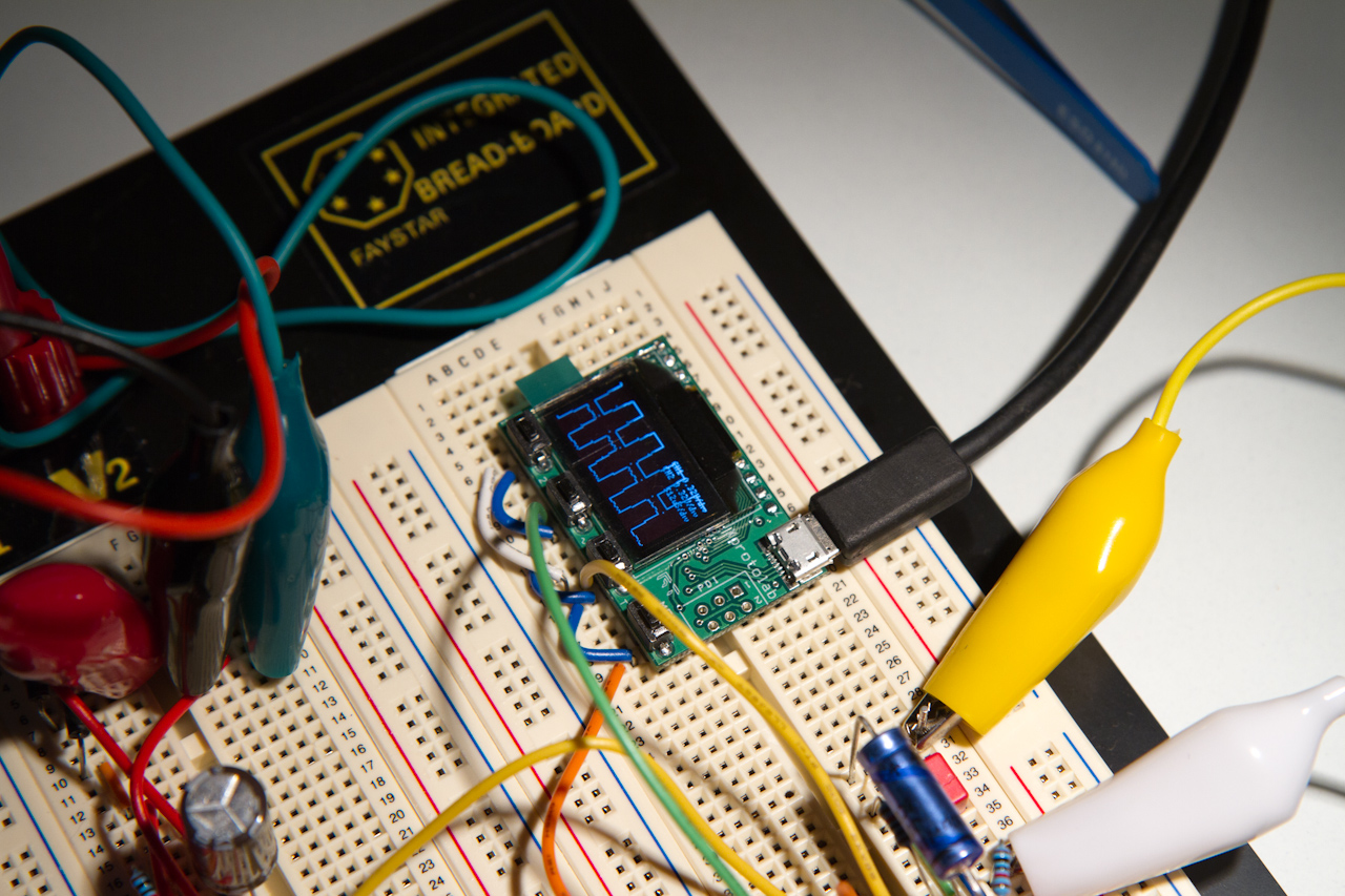
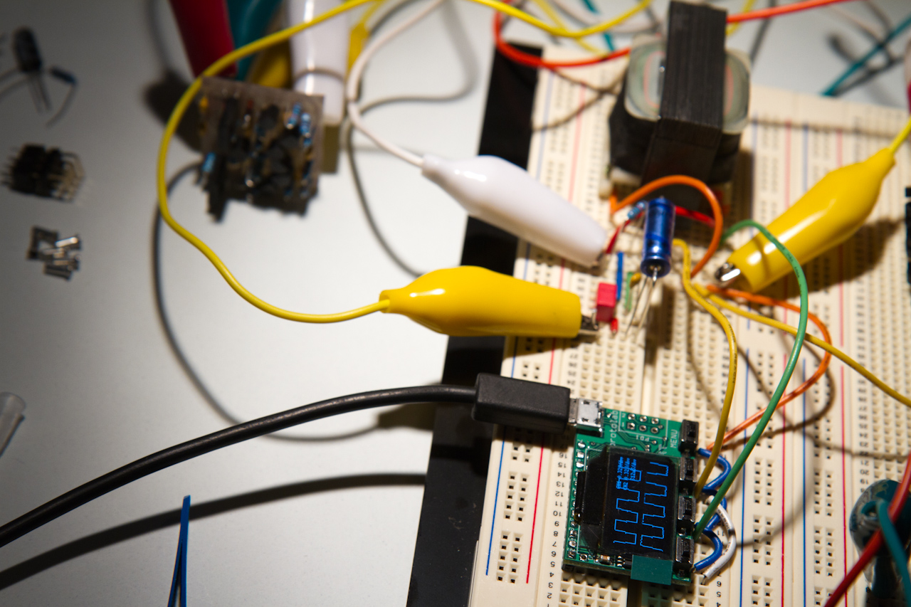
More to come so stay tuned!
A big thanks to Volker and Jeff Steiger, even if they don't know directly they've helped with this project, they have 8)
I am starting this thread to share my experience with DIY'ing a 2500/225L-inspired compressor.
I am working with a schematic I found on this board, that if you really go looking, is pretty easy to find.
I started off this crazy journey with this thread on DIY CNC'ing a 2520 I simulated in LTSpice based on information that I again picked up off this board ( and was not hard to find ): http://www.groupdiy.com/index.php?topic=46998.msg590345#msg590345
There are some basic examples of tests on that DOA at the end of that thread.
Next up, I've taken the schematic and broken it into 3 parts, 1.) The input stage, 2.) The VCA and sidechain circuitry and 3.) The output stage.
Today I verified 1.) and 3.) Next I will work on 2.)
I wanted to share some images of the input and output stage tests.
First here is the input stage, which is a relatively simple, almost text-book, electronic de-balancing circuit based on my 2520 ( in the original it's a 2510, but I haven't built my 2510 yet ):

You can see the Xprotolab in there also assisting me in testing. The top trace is the input, and the bottom trace is the output. You can clearly see that this is an inverting stage with gain 0.5x when run unbalanced ( as here, since one side is grounded, when I input a proper balanced signal it'll be 1x ).
Next up I tested the output stage:

Here you can see the gorgeous Ed Anderson classicapi.com 2623-4 (http://classicapi.com/catalog/product_info.php?products_id=31) output transformer. This will soon be replaced by a 2503 once it arrives - although throughout development I will be testing the sound of both, since I want this to be a character compressor as much as a partial 225L replica. You can also see the rather nice Vishay output cap and WIMA bypass cap.
Here you can see that this stage is also inverting, and this time of gain 1x
Next step is to finish my Eagle board for my take on the 2510 after much tweaking on LTSpice, again entirely based on information found on this board, which I'm going to make in 2520 footprint since it allows for the most options for future expansion ( i.e. I'd love to design some other DOAs and put them in this to see how they sound too.... )
After that, which I hope to all have finished by the start of next week, is the significantly more complex VCA stage, which I'll breadboard up in stages and test also.
I think that the input, VCA and output stages will all go on one PCB just like the actual 225L, and then I can dev the sidechain and control voltages on another, which will aid both development, and simplify the interfacing at this stage. I'm not sure if I'll combine them in the final version onto one PCB or not. Since I'm building 4 of these in one box, that might end up the best option.
Some more images:


More to come so stay tuned!
A big thanks to Volker and Jeff Steiger, even if they don't know directly they've helped with this project, they have 8)


![Electronics Soldering Iron Kit, [Upgraded] Soldering Iron 110V 90W LCD Digital Portable Soldering Kit 180-480℃(356-896℉), Welding Tool with ON/OFF Switch, Auto-sleep, Thermostatic Design](https://m.media-amazon.com/images/I/41gRDnlyfJS._SL500_.jpg)


