An API Compressor Project

GroupDIY Audio Forum

Help Support GroupDIY Audio Forum:

This site may earn a commission from merchant affiliate links, including eBay, Amazon, and others.
Hmmm, talk about public embarrasment.
I could have sworn that's how I wired it in the schematic, but, then again, when you assume something, that's when you do stupid things....
Thanks for picking that up guys, it's much appreciated.
Rectified now ( excuse the pun.... ):

etheory_AC_To_Dual_DC_PSU_v02_01.jpg
 
And here is a compressor "test PCB" that contains the input stage, output stage, VCA and VCA control signal processing bits and pieces.
Next up, now that I've finished some more designs, I will built the 2510 DOA and test it, then PSU and test it, and then this "test board".
That way, I can keep all of the manipulation of the side-chain bits and pieces on breadboard, wire it up to this test board, and tweak away until I am happy.

2012-01-19_API225L_Test_Board_v01_01.jpg
 
Before you etch this, the THAT2180 VCAs pin5 will need a rerouting for a bias setting resistor (with followup IC4-pin4). It is not a direct connection to the negative supply rail. A placeholder for a resistor to reference voltage or trimmable offset voltage at VCAs pin4 might make it more universal for optional using 2181 VCAs. I'd probably place some decoupling caps at the ICs supply pins as well. Might look better than fitting these from traceside, if so needed. YMMV.
 
Some updates!  Since my previous freelance job offer fell through so I found myself a couple more days to fit in some DIY....

Firstly a VERY nice etheory 2510 board variant ready for population ( bottom of screen is a not-so-successful earlier CNC failure of the same board ).
It's sitting next to it's tested and verified bigger brother, the etheory 2520.
I should really rename this the PRR 2510, since it was mostly pushed through the design phase and tweaked in LTSpice by religiously reading his responses to op-amp design and his responses to a thread on the 2510 - so we'll see how well this all works in practice! ( however considering how precisely the 2520 matched the LTSpice simulation, I'm not too worried ).
Also note I've gone for BD139/140 on the output of the 2510 in direct disagreement with the original design.
I've read a lot that the original 2510's tend to "go" rather frequently, so I've slightly over-designed its output stage in an attempt to stop this from happening:

2012-01-20%2B08.50.52.jpg


Also, and a BIG thanks to people on the board for reminding me the discipline of thinking first and posting afterwards, the group-diy-iterated-design PCB for a test power supply, which is currently just partially populated to test part placement, spacing, and drill sizes ( so far so good.... ):
2012-01-19%2B21.31.24.jpg

Note that I'll need to fix the Mach3 CNC software freakout on the right hand corner of the above PCB.  It literally had a fit at the end of that board and started terminator style running across the board before I cut it off.  A computer with a high-speed drill is a bad idea....
2012-01-20%2B08.50.14.jpg


By the end of the day I'll have both of these fired up and ready for testing....
 
Alright! This sucker is now well and truly rollin' 8)

Here is an image of the test PCB, with the input stage (my spin on the API2510), VCA stage (2 x parallel 2180LB's as in the API225L) and VCA driver (NE5534 inverting and non-inverting buffer driving the Ec- and Ec+ VCA inputs), and output stage (my spin on the API2520).

I was just test fitting the main parts in this photo.  I just have to clean, steel-wool polish, lacquer coat and then populate the board now.

All the parts are "final-style" except for the two input caps, which will be replaced by the axial vishay ones when they come.

For those interested here is an album of the process of making the board:
https://plus.google.com/photos/105170802210562791523/albums/5700338432633051617?authkey=CM391af4g8uhqQE
 

Attachments

  • 2012-01-22 19.46.31.jpg
    2012-01-22 19.46.31.jpg
    139.3 KB · Views: 107
OK some more piccies of the test board, which is now completely built, and awaiting some "explosion" testing :p.
Also note the on-board 2510 is now complete and also ready for testing:
MG_8926.jpg

MG_8920.jpg

MG_8919.jpg

MG_8918.jpg

MG_8917.jpg

MG_8916.jpg

MG_8915.jpg

MG_8914.jpg

 
I just fired up the PSU for testing, and no explosion!  YAY!  I have a rock-steady dual PSU for testing ready to go!
Leaving it on for a few mins to see if anything is bizarre, but it's looking great, so that's one off of the list.

I must mention though that the comment in an earlier post about trimmer orientation was correct and I was wrong.  I'll do a slight redesign for next time to get the trimmers going clockwise for more voltage, and anti-clockwise for less.  It's currently backwards :eek:
 
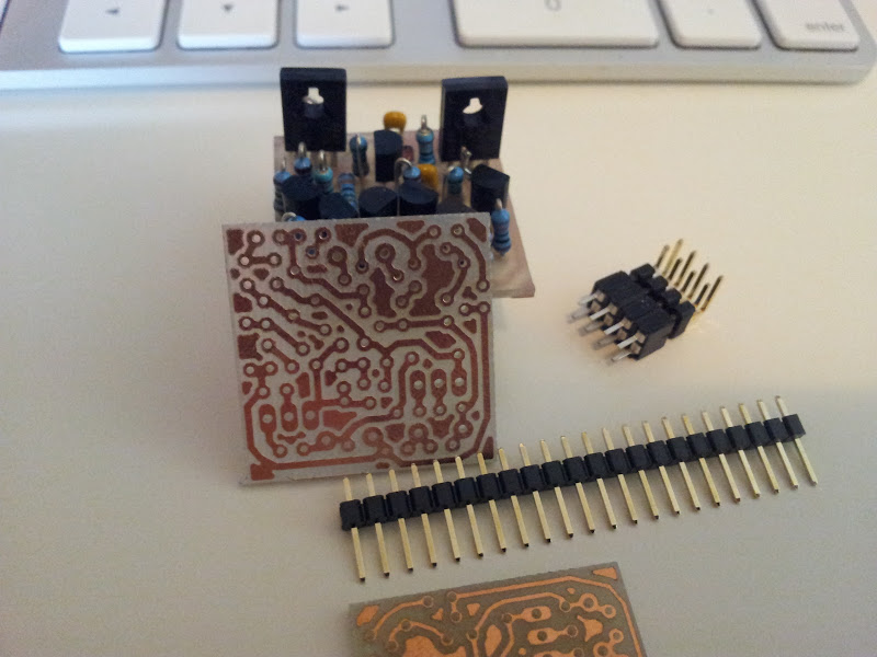
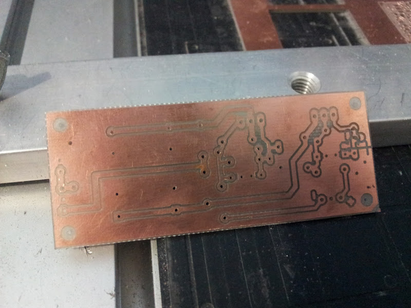
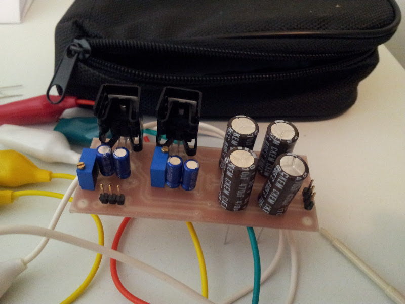
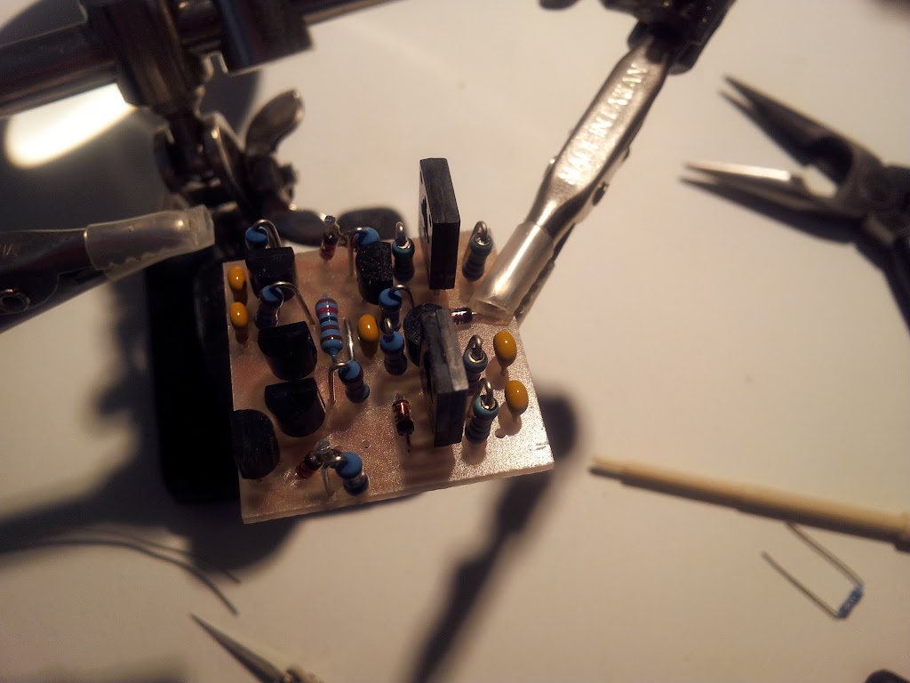
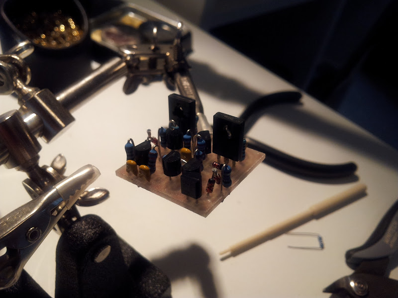
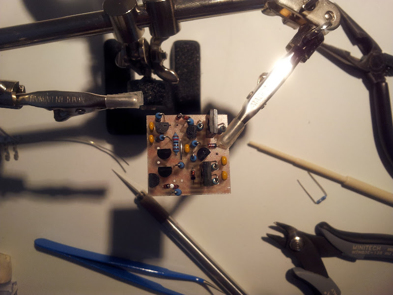
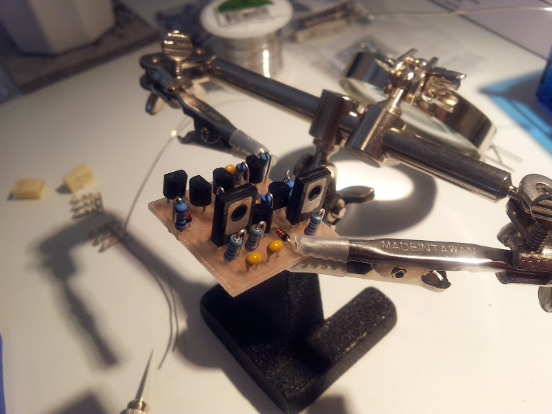
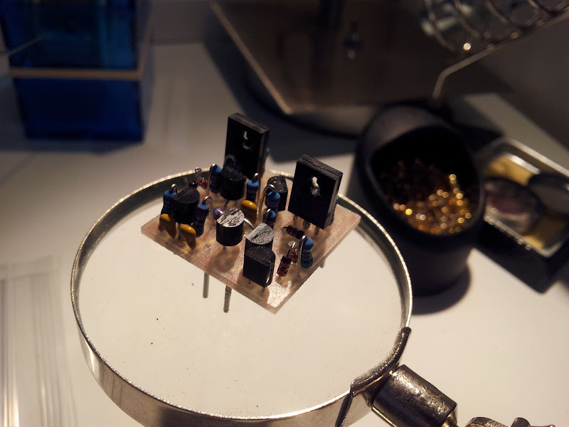
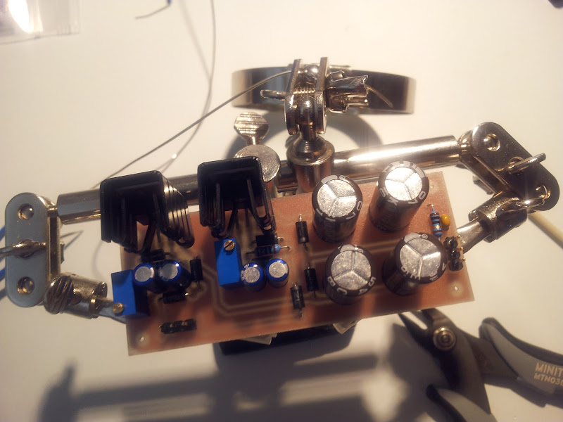
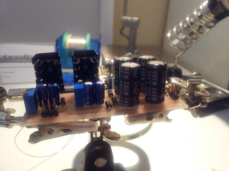
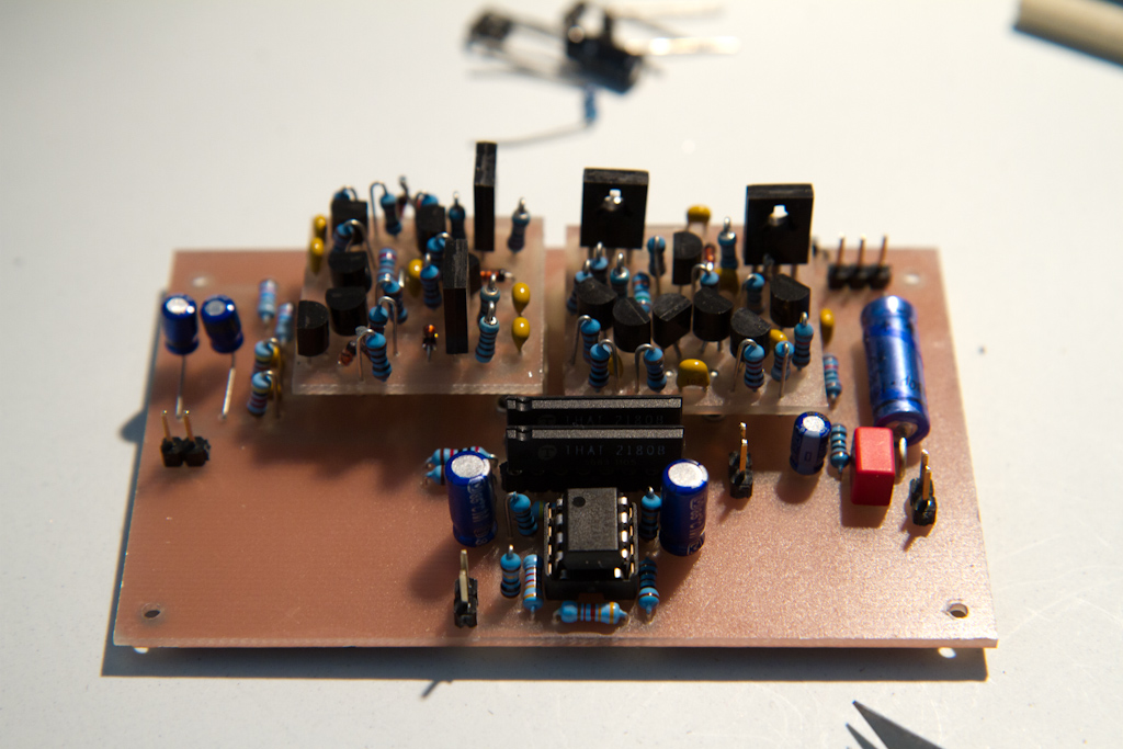
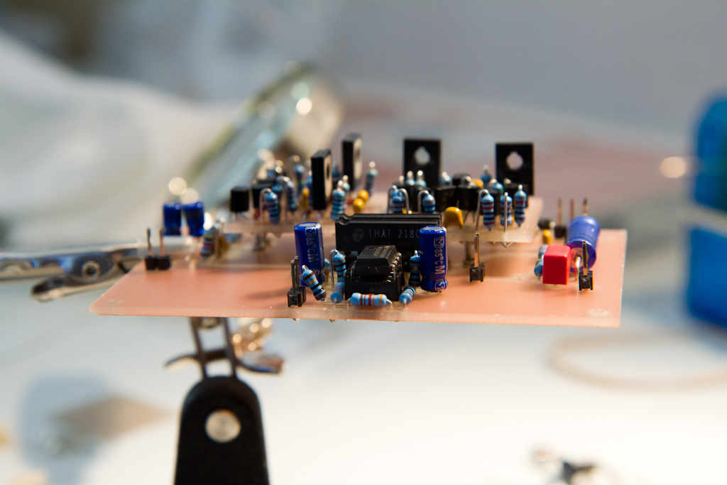
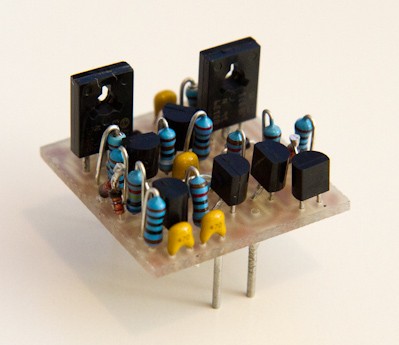
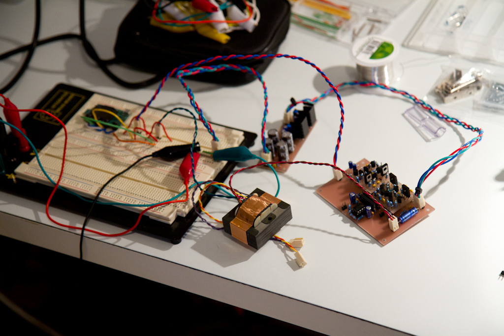
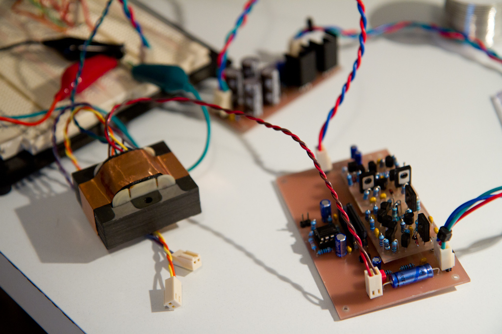
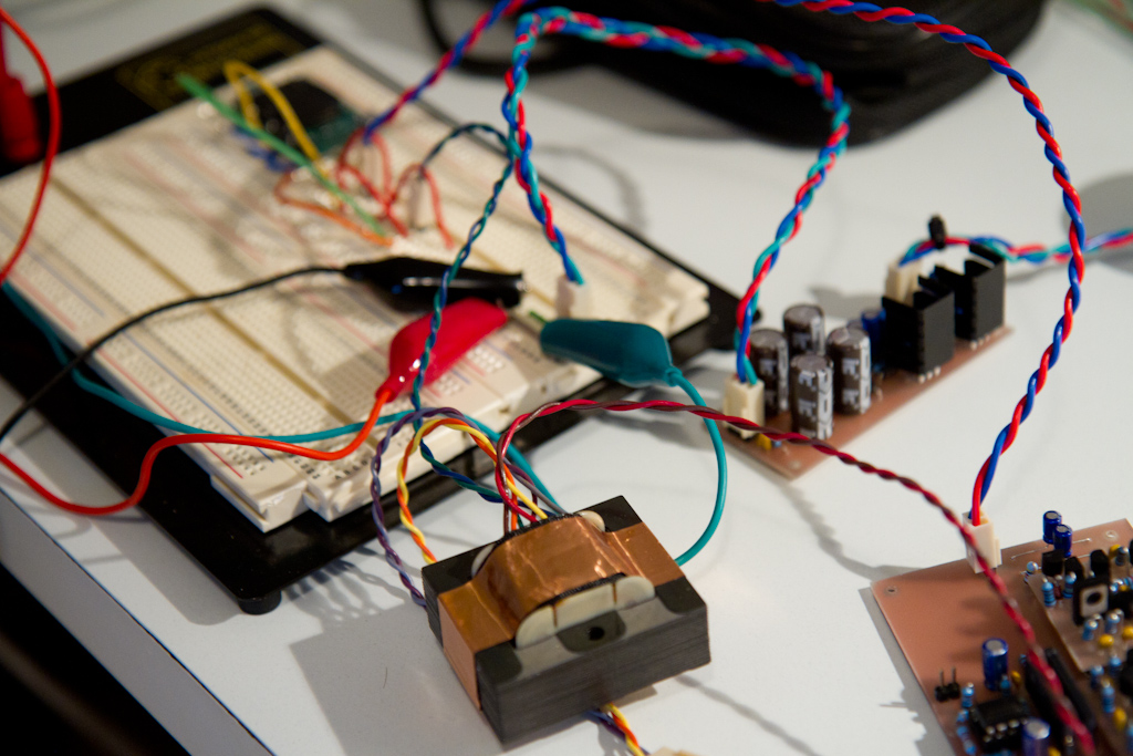
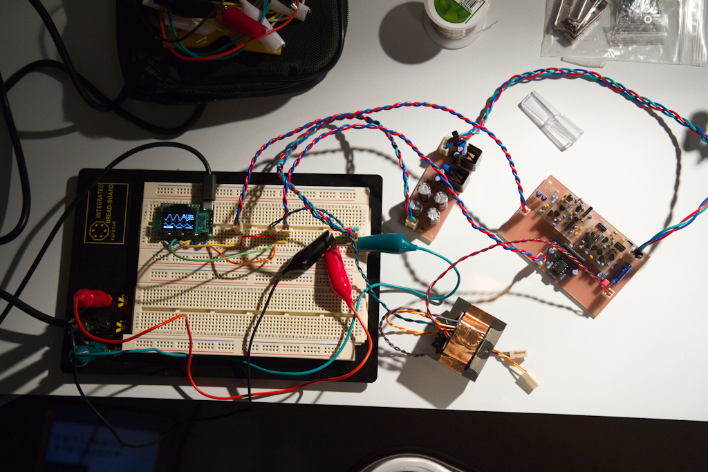
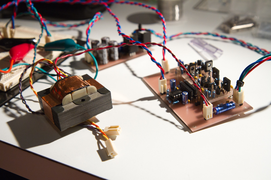
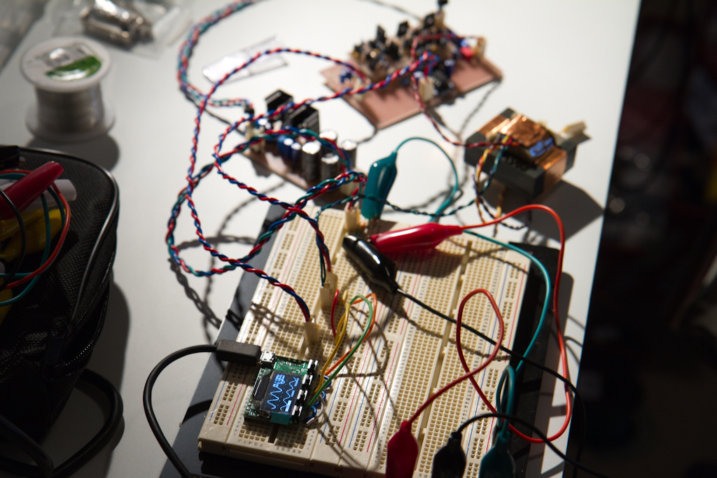
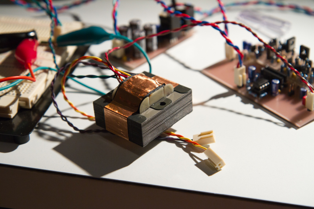
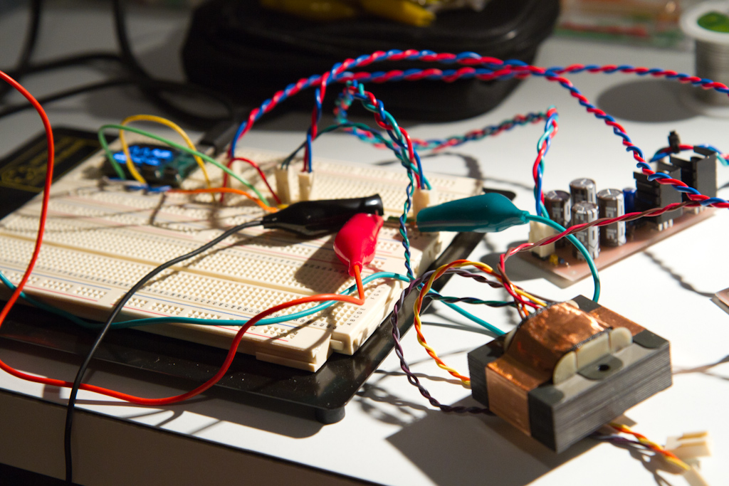
Here are some pics showing the test setup.

I'm quite happy with how the crimp connectors turned out for this purpose.  Very clean and neat which I like, and very easy to change around and manipulate - I'm really glad I went with that method, especially for testing.

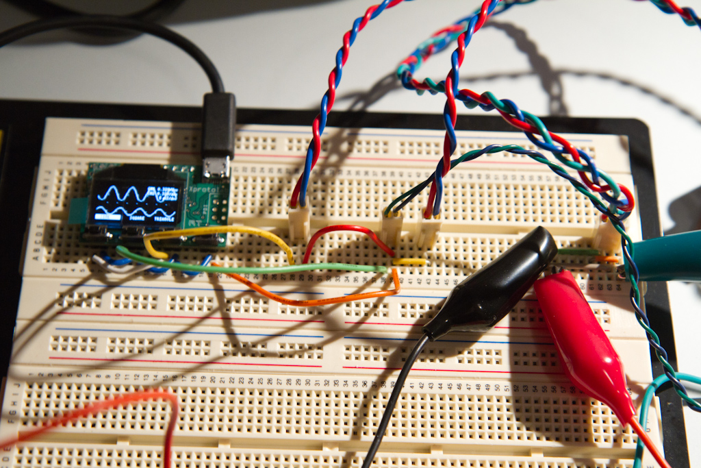
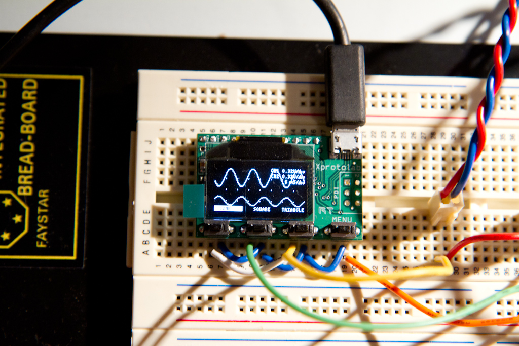
The reason that the bottom trace (output signal) is half the volume of the input is that the input is not a balanced signal, so it's operating as expected (I must remember to test this later also....).  I found out that I'd accidentally inverted the input signal (I had the signal hooked up to the inverting rather than the non-inverting 2510 input) hence the incorrect polarity.  Since taking the photos, I've switched this around to be how it's supposed to be, and now the output is non-inverting as expected.

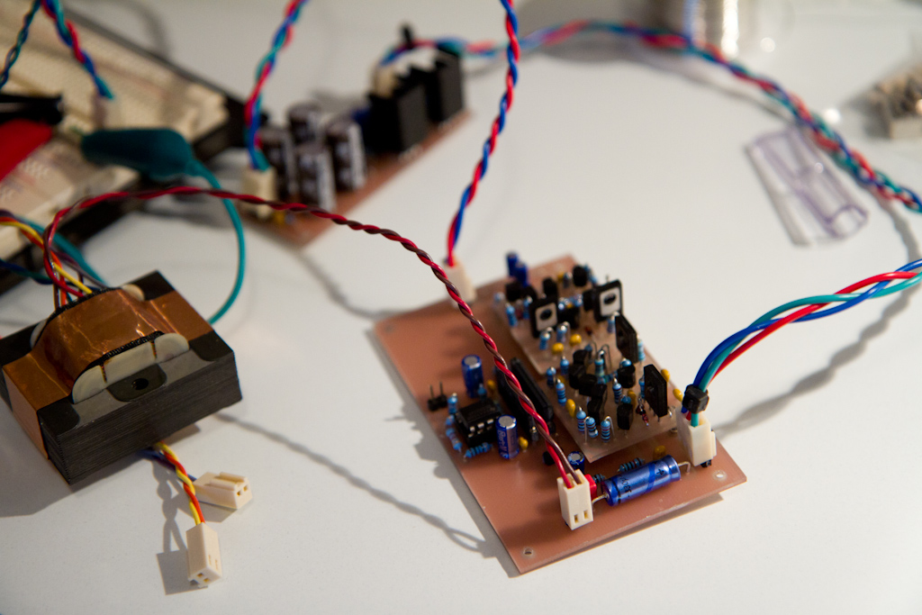
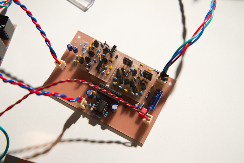
The 2510 is working beautifully and passing a signal, which I am super happy about, since it's the first design I've had to change quite a bit in the simulator from what I found online and cross my fingers and hope for the best.  I'm so happy it works.  I haven't checked the DC offset at it's output yet though, so I'm not sure exactly how good it's really performing, but I'll check this all soon.

The dual 2180LB's that form the VCA are doing their unity gain thing, and the 2520 is driving the transformer beautifully, as expected.

Tomorrow I will try and manipulate the VCA CV input and see if that works as expected too (i.e. more or less volume, ready for experimentation of the side-chain....).
I may have to park it for a while then as I am supposed to start some work this week; but, you never know.... so I'll keep you all posted.

Bed time now, it's been a LONG day at the workbench....

MG_8927.jpg

MG_8928.jpg

MG_8929.jpg

MG_8930.jpg

MG_8931.jpg

MG_8932.jpg

MG_8933.jpg

MG_8934.jpg

MG_8935.jpg

MG_8936.jpg

MG_8937.jpg

MG_8938.jpg

MG_8939.jpg

MG_8940.jpg

MG_8941.jpg

MG_8942.jpg


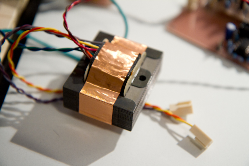
(I can't get over how gorgeous that output transformer is!)
 
Just checked the DC Offset on the output of the 2510 and my little scope has difficulty measuring it, so I will call it negligible and also call it a day.  Awesome.
Would anyone be interested in 2510 boards in 2520 format?  Or would there be only interest for the original footprint?
 
Back
Top