ANT/Telefunken V672 DOA, what to do?

GroupDIY Audio Forum

Help Support GroupDIY Audio Forum:

This site may earn a commission from merchant affiliate links, including eBay, Amazon, and others.

matta

Well-known member
Joined
Jan 11, 2005
Messages
1,640
Location
Cape Town, South Africa
Hey Guys,

I recently purchased a ANT/Telefunken V672D (2 pres in one module) and they have been racked up (not by me, I can't take credit). One of them arrived (prior to being racked) DOA, as it prone I guess with a lot of older gear.

It passes sound at full gain, but is distorted and broken. (I will upload a clip shortly)

Some of the electro's have been swapped out as you will see from the photo below in the hope that it might solve the problem, but alas it did not and I am stuck at square one. There is no smoke on power-up and no parts that seem to have burnt out that are visible. If I leave the unit connected the PSU regs do get rather hot quite quickly.
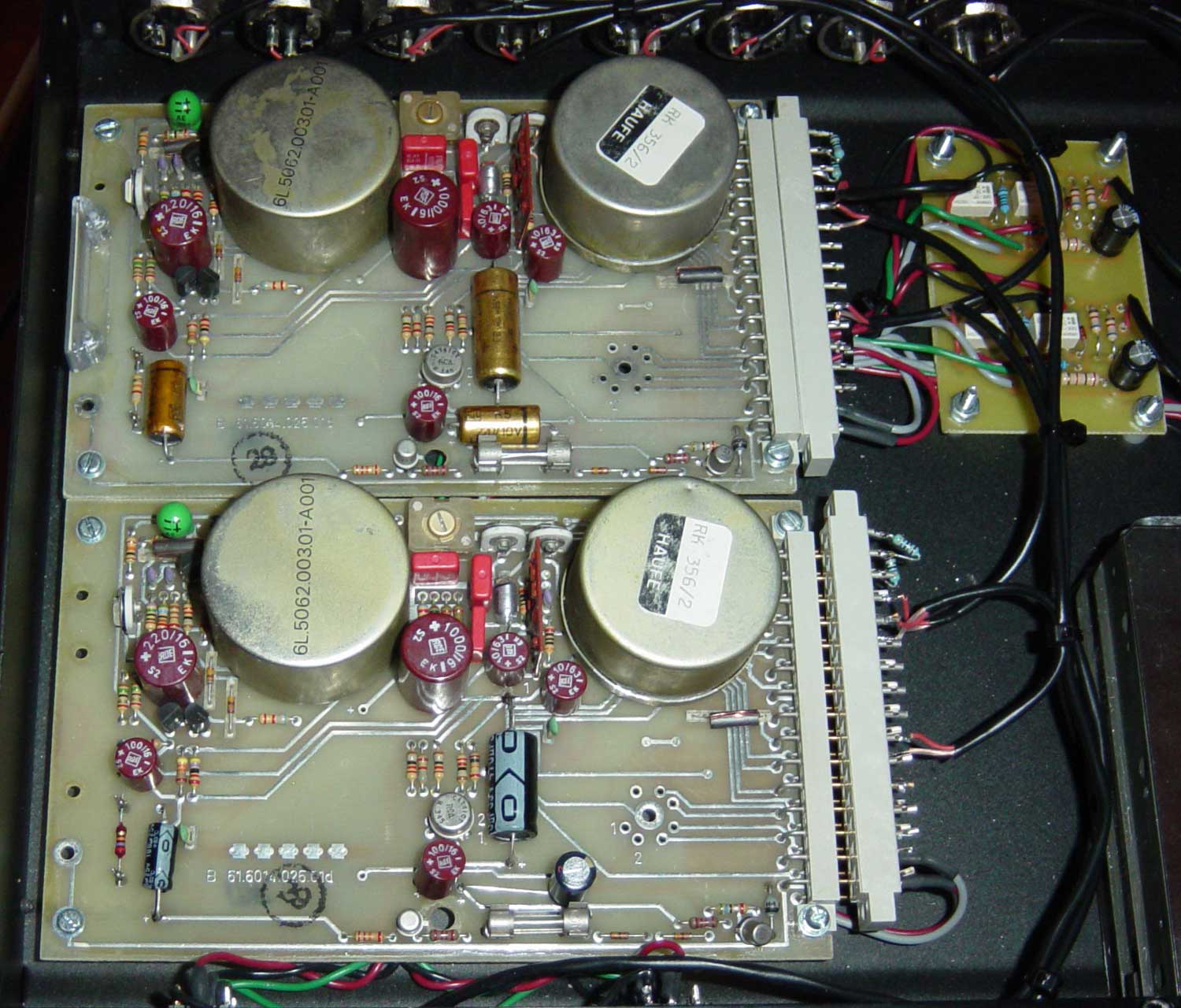
boards.jpg


The pinouts are correct as the other module is 100% fine (and sounds great), but this one is not.

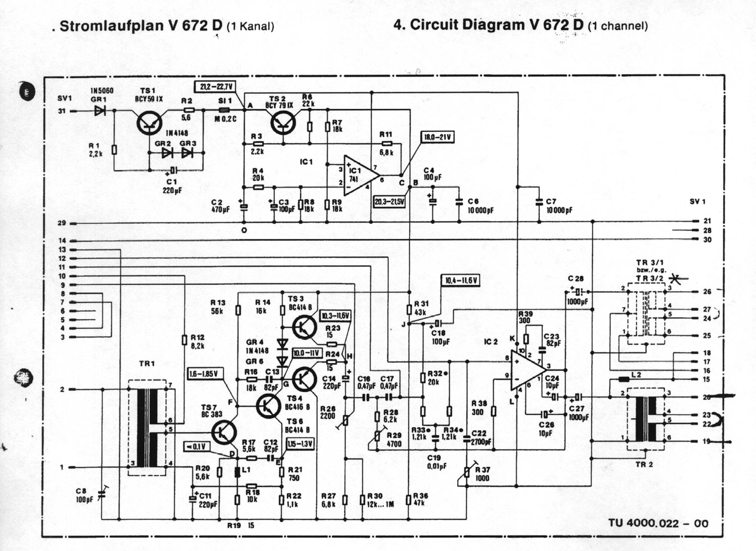
I've been able to get hold of the parts overlay and schemo which I post below.
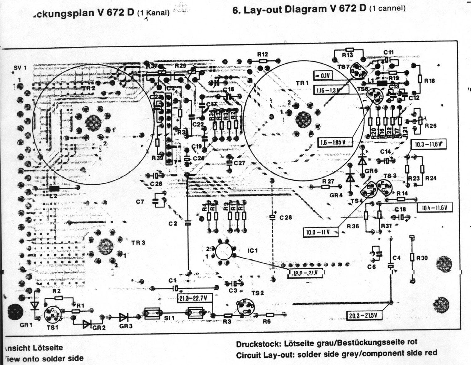
parts.jpg


schemo.jpg


Does anyone have advise or experience with servicing these modules or could point me in the right direction of where I could start trying to trouble shoot this? As alot of you know I am still a newbie having built only a handful of gear and only basic trouble shooting skills have been acquired. I am limited to my my DDM but have access to scope if needed.

I'm keen to learn more and would love to try and get this guy back up and running. I think most parts should be replaceable except the op amps and tranos, so I hope it is neither one of them that has released it's smoke.

Any suggestions would be most helpful, thank as always!

Cheers

Matt
 
Hi Matt,

Have you checked your supply voltage? Follow +24V in from pin 31, and make sure that you're getting 20 or 21V at the collector of Transistor #3, and that 22V-ish is getting to the IC pin 10.

The best way to find a fault in a circuit like this is signal tracing, and this is a nice simple circuit to get to grips with it. Check the link here for details on how to roll your own.

Hope this helps, and let me know if you need any more details.

:thumb:

Mark
 
Hi Mark,

Thanks for the insight as always! I thought of you today as I enjoyed yet another cup of Earl Grey :thumb:

I remember seeing your signal tracer around and thanks for the link, it is book marked and on my TO DO ASAP list, in fact it just made #1 :green:

I checked those V's and they were way off. I was getting 9,5V where I should be getting +20V as you mentioned.

I then retraced to junction after the fuse (S1) and before the emitter of TS2 where there schemo calls for between 21,2 - 22,7V and got 9,7V!

I then checked it against the working one and it read 22,3V at the same junction....

I basically then traced it all the way back to Pin 31 and the voltage up to the collector of TS1 and it remains 23,7V (the input V at pin 31) but then the V at the Base is 10,4V and the Emitter is 9,7V.

Is it a safe guess to say I have a blown transistor :shock:

If that is the case what would be modern day equivalent for it. From what I gather from the schemo is it a NPN.

Do you or anyone else know what a replacement for BCY59 IX would be? Or in anyone knows where I could get NOS, or has one I could buy?

Thanks guys, I hope this blown transistor has not caused any other damage to the circuit.

Cheers

Matt
 
I finally got around to trying out my new Peak DCA component analyzer on the the suspect NPN transistor I pulled from the NF module and these are the read outs for BCY59 IX

NPN Silicon Transistor
Current Gain: Hfe = 351
Test current Ic=2.50mA
Base-Emiter V Vbe=0.77V
Test Current Ib = 4.53mA
Leakage current Ic=0.00mA

I'm not sure if that is any help at pin pointing any errors, but thought I'd post them none the less.

Cheers

Matt
 
Well,

If they're the readings from the BCY59 from the faulty module, you'd better get your faultfinding hat on and a big mug of Earl Grey- that seems to be a perfectly functioning transistor! Are you sure you've written the base current down correctly? The hfe reading shows good transistor action.

That input transistor is effectively a current-limiting stage- it means that the peak current under a fault condition is limited to about 250mA. This is what you're measuring- the voltage has been reduced as the circuit is drawing more than usual current. This points towards a fault further into the circuit. Take out the fuse S1 and then measure the voltages around TS1- it should go back to normal.

The output driver IC2 is a possible suspect, but a signal trace will quickly find the problem.

Looks like that Atlas is coming in handy!

Mark
 
Hi Mark,

Thanks for the feedback. Firstly those are the correct readings from the Atlas on the 'faulty' tranistor and the HFE is confirmed by the datasheet, which prob means that is not the issue! Damb and I thought this would be easy....

I am in the process of making the signal probe. I am just short the pot.... the pot... not pot.... LOL! Will try pick one up durning my lunch break tomorrow.

Any tips on where I should start the signal trace?

Thanks again :thumb:

Cheers

Matt
 
replace those electrolytic caps! I've had a couple of ANT units where the caps fail to almost short-circuit, which is quite an unusual fault for an electo...but there you go. Just last week i had an ANT unit that the supply volts was down to 2.5V due to a bad cap.
 
Thanks Squib,

Which Electro's? All of them? There are still 6 unchanged original electros and the tant cap.
Mark would the probe show up the caps as being bad?

As promissed here is the clip of me talking into an SM58 at full gain, and the recorded output.

ANT Distortion

Thanks again for all the help.

Cheers

Matt
 
yeah do the lot, why not, and include that tantalum, 'cause they can definitely fail short. C1, C2, C3, C4 are all involved in the power supply section and could be a source of your troubles.
 
Good advice from squib there- electros often go short-circuit (s/c) when failing- I've chased faults for hours before now, and missed an obvious s/c cap. There are lots of culprits here- C2, C3, C4, C6, C14, C18, C27 would all cause power supply and signal path faults.

You can check these out with a DMM set to "Ohms" range- a healthy cap will be empty at first, so the readout will flash low-ohms for a second, and then (hopefully!) go up to "infinity" once it's fully charged. However, it is often misleading because of other components in the surrounding circuit- most notably resistors- their value appears in parallel with the cap. Often a short circuit cap will be below 500R though, so it's fairly easy to spot.

Also, for quick testing, you can lift one end of a suspect PSU decoupling cap- if any of C1, C2, C3, C4, C6 or C18 are the culprits, lifting by desoldering one end will find the faulty one. When the duff one is out of the circuit the PSU rail will lift back to normal.

Signal tracing can find a faulty cap- it depends where it is in the circuit. It's handy for finding a faulty cap in the audio chain, not so good for a s/c power supply decoupling cap, as this will corrupt the audio throughout the circuit.

I discounted a cap fail, as I skim-read your post that you'd replaced the caps- I just looked at the pic and saw that you've only replaced a few!

It'll be worth replacing them anyway- old electro caps are rarely good caps (despite what people might say :green: )

Mark
 
[quote author="squib"] the caps fail to almost short-circuit, which is quite an unusual fault for an electo....[/quote]

...I don't know, I've had a lot of trouble with those yellow "Frako" caps in Studers and lots of German broadcast modules- they seem to very suddenly go s/c to less than 50R or so, with no smoke or mess! They do get warm to the touch though...so annoying!

:roll:

Matt- if you need to sig trace, here's a pointer to the "hotspots": V672 Signal Tracing Diagram

You should be able to trace audio at all these points. When it disappears, or gets noisy/distorted, that's the area of interest.

Mark
 
SHE IS A WORKING!

Squib, hats off to you for the cap suggestion and Mark for pointing out the spots to check on...

I re soldered the transistor in place and removed the 2 x 10uF electro caps and replaced them with some new ones, and just out of interest powered up and the V was back up to 22V.

Thew up a mic and hit record, and back to normal!

So she is a working now, but while I am at it do you think I should replace ALL the lytics, even if I have solved the problem? How much of a difference, if any will the old caps contribute to the sound of of the ANT?

When you guys do refurbs or racking do you tend to replace all the caps?

Thanks again for sharing your wealth of knowledge, it is much appreciated.

I'm still going to wrap up my probe this week as I think it is an awesome addition to my somewhat lean troubleshooting tools.

Cheers

Matt
 
Mark,

I just wanted to say a big thank you again, esp. for all your hard work on that tracing diagram, I owe you a :guinness: !

I'll actually be in London for 2 weeks over Xmas so if you are around it would be good to meet, I owe you one at the local!

Cheers

Matt
 
Cool!

...and minimum of tea spilt :wink:

It's a real buzz when you get something back on the road!

Replacing caps- it depends on the situation. If it's an old module that's seen a lot of use, and it's going to be used 24-7 in a pro setup, I usually replace all the electrolytics. This is for sound and reliability.

There are only a few electrolytics directly in the audio path here, and changing them will cause minimal difference to the sound. In 99% of cases fresh electrolytics do wonders for the sound- especially the LF.

Back to the recording!

:thumb:

EDIT> Just saw your post- cheers! Keep in touch- not sure where I'll be in Dec, but I'll let you know. A bunch of us are meeting with Jakob in August- shame it doesn't match up with your visit!

Mark
 
I def. have that buzz right now! I am so glad I'll be able to use it! I can't believe I just fixed my own pre.... a few short month ago I was paying someone to make my mic cables now I have build 2 pres from scratch, an EQ and now this... and it is beginning to make some sense ;-)

Thanks for the input on recapping, I'm missing a few values right now, but am think to buy some in just in case and on a not so busy day maybe spend more time with these pres and a nice hot iron... and a cuppa.

I only got through 2 cups of Earl Grey today! But alot of hours spent on this one :) It is 2 am and I finally going to get some sleep ;-)

Pity I won't be there in August! I will be there mid Dec till early Jan, I am hoping to hook up with a couple DIY'ers while I am over there. Pity I will mis Jakob but I vowed to one day take a trip to DIY Mecca.

Cheers

Matt
 
Hello,
really old thread here,
but I'm working some V672 units at the moment and need some help.

Any chance anyone around here still has the V672 Signal Tracing Diagram document?

thank you so much
 

Latest posts

Back
Top