efinque
Well-known member
- Joined
- Jan 3, 2018
- Messages
- 368
Sup GDIY,
I've been working on an Arduino-based optocompressor while recovering from my DIY spree.
Basically it takes the audio input and the MCU lights up a LED once the signal reaches a defined threshold level. The LED then controls an LDR which feeds an audio output. The LED has a defined hold time, I've been doing tests with 10-500ms.
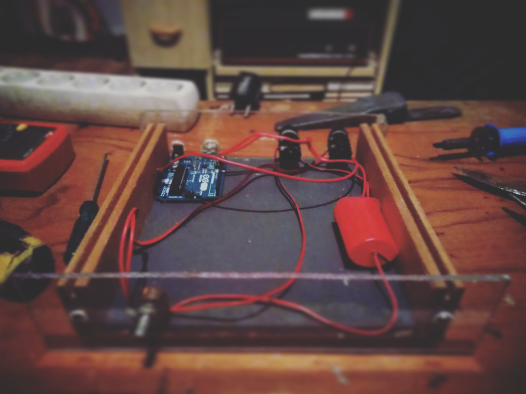
Here's a build pic with the volume knob, connectors, MCU board and the control circuit in place (I packed the optocoupler inside a tube which is used to hold camera negatives)
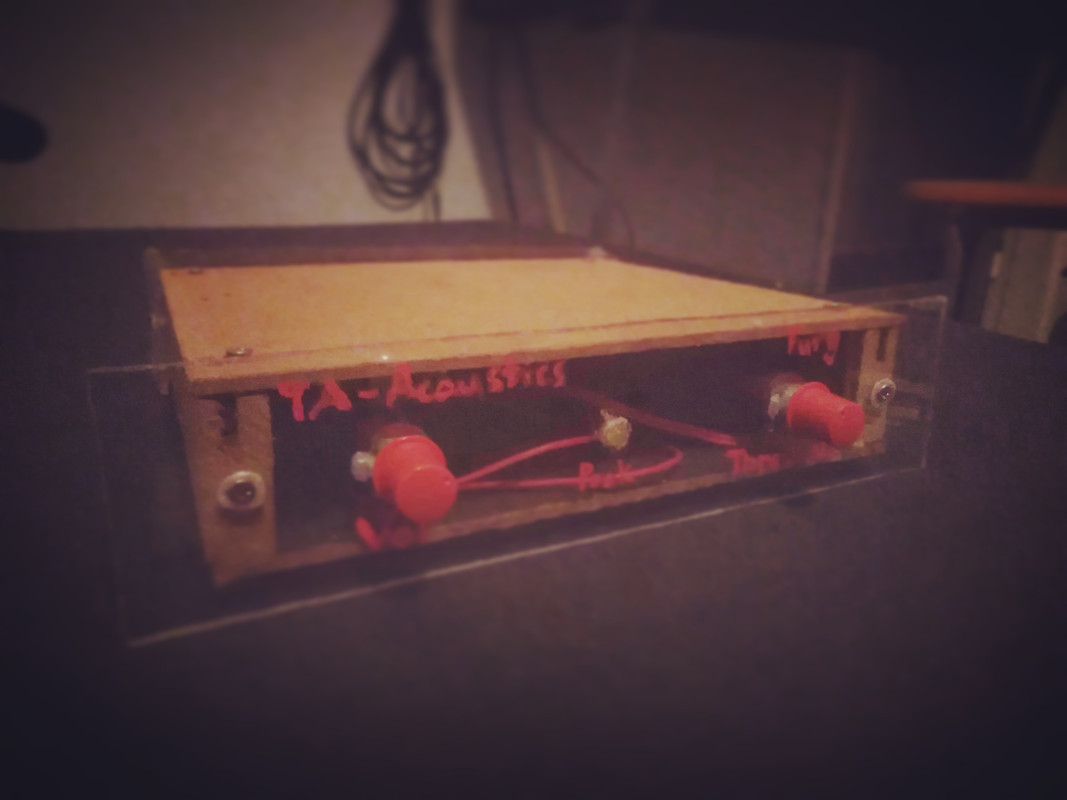
And the finished unit with a peak LED and threshold.
I'll post a schematic and the code later.. for now the threshold adjustment doesn't work, my serial monitor shows 1023 (=5V control voltage from the board) so I think the input pin could be damaged since I've been using the board for prototyping for about a year.
I was thinking of adding a sidechain, and a pad/potentiometer to set the hold time as well as getting rid of the threshold control (ie. making it fixed value, I used 700 which was ok for the equipment I was using, the maximum value for 10-bits is 1023) and adjusting the input instead.
Anyway, what do you think?
-ef
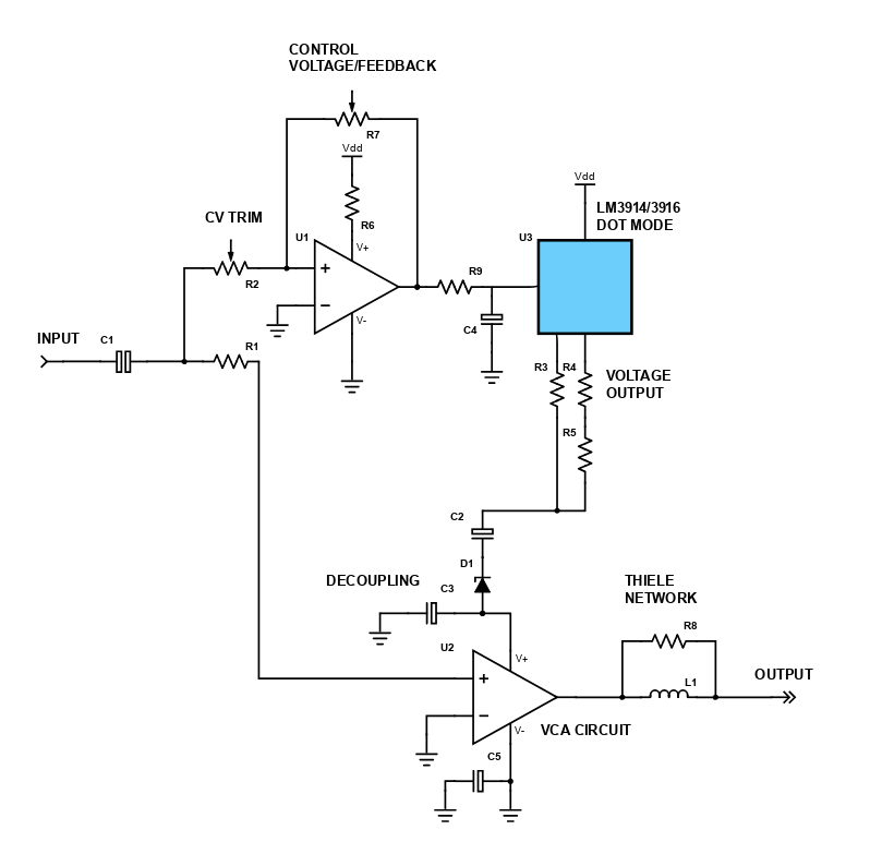
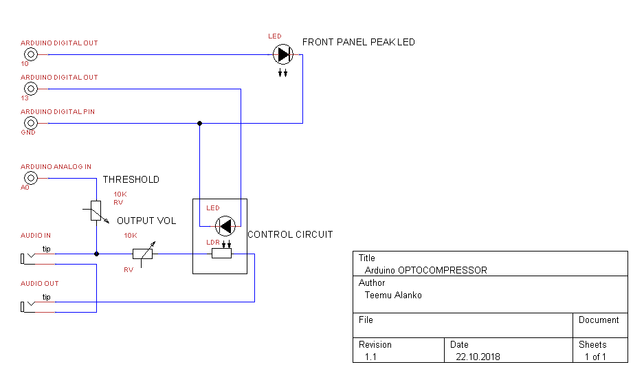
EDIT : here's the schematic :
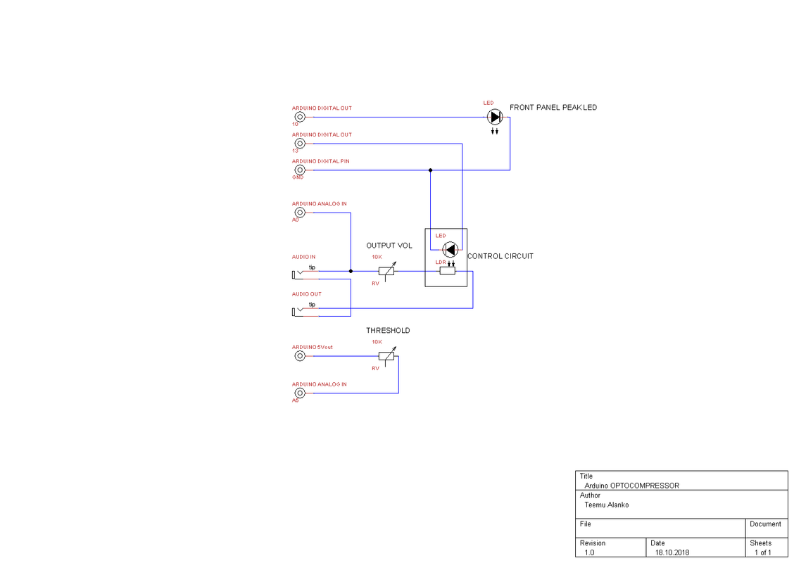
(my CAD didn't have a photoresistor symbol, I put a normal one there instead)
and the code :
EDIT 2 : oh, and a make-up gain too... tbh it's more like a gate though. I tried other input pins too, maybe it's the potentiometer acting up (I pulled them off an old reverb unit as well as the connectors) At first I was doing tests with a simple Schmitt trigger but it didn't work so I put the Arduino to good use.. it didn't have enough I/O for a synth project I was planning anyway.
I've been working on an Arduino-based optocompressor while recovering from my DIY spree.
Basically it takes the audio input and the MCU lights up a LED once the signal reaches a defined threshold level. The LED then controls an LDR which feeds an audio output. The LED has a defined hold time, I've been doing tests with 10-500ms.
Here's a build pic with the volume knob, connectors, MCU board and the control circuit in place (I packed the optocoupler inside a tube which is used to hold camera negatives)
And the finished unit with a peak LED and threshold.
I'll post a schematic and the code later.. for now the threshold adjustment doesn't work, my serial monitor shows 1023 (=5V control voltage from the board) so I think the input pin could be damaged since I've been using the board for prototyping for about a year.
I was thinking of adding a sidechain, and a pad/potentiometer to set the hold time as well as getting rid of the threshold control (ie. making it fixed value, I used 700 which was ok for the equipment I was using, the maximum value for 10-bits is 1023) and adjusting the input instead.
Anyway, what do you think?
-ef
EDIT : here's the schematic :
(my CAD didn't have a photoresistor symbol, I put a normal one there instead)
and the code :
Code:
void setup() {
  Serial.begin(9600);
  pinMode (A0, INPUT);
  pinMode (A5, INPUT);
  pinMode (10, OUTPUT);
  pinMode (13, OUTPUT);
}

void loop() {
  int controlV = analogRead(A0);
  int threshold = analogRead(A5);
  int hold = 500;
  Serial.println(controlV);
  Serial.println(threshold);

 if (controlV > threshold) {
    digitalWrite (10, HIGH);
    digitalWrite (13, HIGH);
    delay(hold);
      }
    else
      digitalWrite(10, LOW);
      digitalWrite(13, LOW);
  }
EDIT 2 : oh, and a make-up gain too... tbh it's more like a gate though. I tried other input pins too, maybe it's the potentiometer acting up (I pulled them off an old reverb unit as well as the connectors) At first I was doing tests with a simple Schmitt trigger but it didn't work so I put the Arduino to good use.. it didn't have enough I/O for a synth project I was planning anyway.
")