Balanced/hum bucking spring reverb recovery

GroupDIY Audio Forum

Help Support GroupDIY Audio Forum:

This site may earn a commission from merchant affiliate links, including eBay, Amazon, and others.
I noticed triboelectric effects with regular mic and starquad cable into hi-z balanced , two short lenghts of noiseless instrument cable was what I found best in the end .

I have mounted a TRS socket on the tank before. I found the open style Switchcraft to fit well and allow good clearance with the sub tray .

I think I prefer to avoid the possibility of anyone plugging or unpluging cables directly on the tank because it could cause an unpleasent noise , a pre-defined cable lenght keeps capacitance a known quantity and provides physical isolation from the tank also .

I picked up a few strips of fridge magnet material , it has some curious properties .
the printed side of the material exerts much less magnetic force than the magnetic side ,
to the point even two strips of the material wont stick ,
flip them so both magnetic sides are facing it will stick and hold , it appears it has north/south magnetic poles in one direction through the material in lines ,so if you pull two pieces against each other they alternatly stick then repel then stick again .

It seems to have a good damping effect on the springs motion when you get around 2-3mm away , downside is it obviously deflects the spring and magnets from their normal resting position ,
The effect of the magnet is to reduce and damp any large low frequency excursions of the spring due to vibration , the tiny higher frequency rotational movements of the spring under normal usage arent effected much at all .

I stuffed the sub tray springs loosely with small piece of felt , that again had a beneficial damping effect if the tank gets a physical knock or vibration .

Into the usual hi-z tube recovery I seem to remember the higher impedence coils always sounded more crisp and clear with more output level but were worse in terms of suscepatbillity to magnetic feilds with unbalanced input .
 
I tried a few readings on the LCR with various tank coils and they are well within the ball park figures suggested ,
2250 ohm pickup coil gave 341mH @1khz .

It seems the rotational movement and the decay time of the spring are primarily controlled by what they call damper disks behind the magnets , that bit I didnt know .

Theres a good overview of the mechanical properties here ,
http://www.accutronicsreverb.com/pages/works.php
 
I just discovered another tank I have has an open circuit pickup coil ,
its of the type in the pic below , with the plastic mini connector ,
Theres a lot of complaints about these kinds of transducers breaking as any movement of the sub tray exerts a force directly on the tiny magnet wires ,which finally fatigue and get broken .
My advice is go for the kind where the connecting wires are taped onto the bobbin in the old fashioned way .transducer.jpg
 
I just discovered another tank I have has an open circuit pickup coil ,
its of the type in the pic below , with the plastic mini connector ,
Theres a lot of complaints about these kinds of transducers breaking as any movement of the sub tray exerts a force directly on the tiny magnet wires ,which finally fatigue and get broken .
My advice is go for the kind where the connecting wires are taped onto the bobbin in the old fashioned way .View attachment 120233
I've found that once that JST connector is inserted onto the pins it can't be removed without risking breaking the wires. And yes they are potentially super-fragile when placed in service.

WRT to the damper material. This was sent to me by Hynn Park of Accu-Bell.
Accutronics_damper_sleeve.jpg
 
I was very happy to replace spring reverbs with digital EFX inside powered mixers. as soon as the digital EFX became acceptable to customers. My engineers working for me appreciated the easier interface.
===
I recall when Peavey started making cheap guitar amps in China, we had so much trouble sourcing reverb pans locally that didn't suck, that we had to ship US made tanks to China for the early production. I expect they got it sorted over time, but not my area.

JR
 
I was aware of the disks inside the brass tubes alright , just didnt know they were involved in adjusting the decay time .

I was around during the changeover from springs to digital FX , the extra presets were a very welcome addition to mixers .
Something I noticed about the Peaveys was very often the FX went wonky after a while , there was still some kind of an effect came out but typically the presets didnt fuction as they were supposed to anymore . I got countless units in for repair , but the cost of the replacement board , for something that in all likelyhood would fail again ,I wasnt going to take the chance ,and recomended the customer use an external Fx unit instead .

Trying to place a reverb tank in close proximity to a very large transformer inside a powered mixer ,thats probably not easy to do and avoid magnetic interference at the same time .
We saw the lenghts Fender had to go to to make his standalone reverb quiet .
Im just suprised more amp manufacturers didnt try a twin tank arrangement ,
the extra springs adding noticably to the smoothness of the decay ,while humbucking coils greatly reduce the magintude of any nearby sources of noise .

It clearly states in the Accutronics docs that opamps alone provide marginal drive capabillity , suggesting something more like a small speaker driving amp is whats needed , the same advice was echoed by many on forums and it fits with my own experience ,
Even the tank drive in most tube amps is a bit marginal , tubes are run flat out, often not far off full HT voltage , they need changing out much more frequently than other preamp tubes .
 
I was around during the changeover from springs to digital FX , the extra presets were a very welcome addition to mixers .
me too
Something I noticed about the Peaveys was very often the FX went wonky after a while , there was still some kind of an effect came out but typically the presets didnt fuction as they were supposed to anymore .
I don't have any first hand experience with troubleshooting these pups but IIRC the selector switch was a rotary encoder (?) connected via a ribbon cable. Dodgy efx selection might suggest looking into that switch/cable.
I got countless units in for repair , but the cost of the replacement board , for something that in all likelyhood would fail again ,I wasnt going to take the chance ,and recomended the customer use an external Fx unit instead .
I am not aware of any disproportionate failure pattern. These powered mixers were pretty large sellers.
Trying to place a reverb tank in close proximity to a very large transformer inside a powered mixer ,thats probably not easy to do and avoid magnetic interference at the same time .
Bingo. I was pretty much stuck with what the digital group gave me, but the performance of the early digital efx boards was pretty marginal. The digital lads used lots of HF pre/de-emphasis in the reverb algorithms to improve S/N-noise floor. Sadly on some of the reverb presets, the HF headroom was almost non-existent. They graciously gave users a red blinky LED to indicate saturation (probably some register overflow flag). I suggested to the digital boys to instead take that LED overflow LED flag to drive a simple JFET limiter and compress loud HF passages only when and only as much as needed to prevent OF. I scratched out a simple (analog) limiter circuit for one of the junior digital engineers to implement and it worked. Still not hifi but sucked somewhat less. :unsure:
We saw the lenghts Fender had to go to to make his standalone reverb quiet .
Im just suprised more amp manufacturers didnt try a twin tank arrangement ,
the extra springs adding noticably to the smoothness of the decay ,while humbucking coils greatly reduce the magintude of any nearby sources of noise .
I don't know if it was quite that easy, and Peavey was a sharp pencil organization.

JR
It clearly states in the Accutronics docs that opamps alone provide marginal drive capabillity , suggesting something more like a small speaker driving amp is whats needed , the same advice was echoed by many on forums and it fits with my own experience ,
Even the tank drive in most tube amps is a bit marginal , tubes are run flat out, often not far off full HT voltage , they need changing out much more frequently than other preamp tubes .
One of the reasons why I was looking for the inductance values is to evaluate the drive requirements.
In the particular case of the 10 ohm drive, it requires a peak-to-peak voltage of about 7V (5Vrmd) to produce the nominal current of 26mA at 10kHz.
I used a TL072 with a complementary pair to make sure I had some headroom.
I'm not trying to re-issue anything, rather refresh my faded memories, and maybe help a little those who embark on this project.
 
From my 2019 post on the subject of driving Accutronics reverbs.

"My reverb experiments have shown me that a zero ohm output with equalized drive to simulate constant current is the way to go.
It just sounds better. MicMix MasterRoom XL-305 Spring Reverb Clone - Page 6 - Pro Audio Design Forum

Constant current drive, or an approximation of it, is necessary with highly inductive drive transducers.
Current, not voltage, does the work.

The reverb is using two Type 9 drivers in parallel to maximize electrical damping.
The transducers represent a 5Ω load at 1 kHz.

At high frequencies, where the impedance of the driver transducer is much higher, a correspondingly larger peak voltage is required to maintain the same level of current.
At the recommended nominal drive of 56 mA RMS (two transducers) only 280 mV drive is required at 1 kHz.
With 30V supplies the amount of voltage available, versus the amount of voltage needed, is quite large.
While there is plenty of voltage and current headroom in the driver, current headroom in the transducer is limited by distortion and burn-out.

If we assume that 10 dB overdrive is a satisfactory headroom margin for a reverb, then the peak current works out to be just under 250 mA.
The approximate measured drive voltages at 250 mA peak current are:

100 Hz 600 mV p-p
1 kHz 2.5 V p-p
5 kHz 10 V p-p

Voltage across the transducer is obviously not a good way to measure transducer current or overload.

At DC the transducer resistance is below an Ohm - wiring resistance and the output impedance of the driver have an effect on LF response.
A simple form of current limiting is needed without introducing any DC resistance in the output.

Taking feedback from the load side of a output build-out resistor could keep the output impedance low but, with an inductive transducer, stability would be a problem.
Some other form of simple passive current limiting would be better.

At what current do the Type 9 transducers burn out?
I don't know and don't want to find out. (I've driven them up to +20 dB over for a short time and they complained loudly.)
At some point however a dash-board light needs to light up and signal "Stop this."

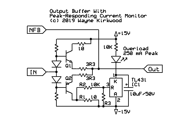
Enter the TL431 peak flasher "winky"

Current_Shunt_Monitor_1.png

A peak responding current shunt monitor using a TL431 as a comparator to indicate driver overload. Circuit fragment with driver op amp not shown.


The driver op amp is not shown...
To limit available current to values that are hopefully "safe" under extreme overload conditions, the old trick often used in headphone amplifiers of adding collector resistance is used here.
Resistors at the collectors of the output transistors collapse the supplies under extreme current overload.

Because the collector resistors are inside the feedback loop they don't raise output impedance until they begin to collapse.
Its crude over-current protection.
For this application a value of 10-20Ω seems about right.

(The 3R3 and 10R resistors are "defined interruption" 1W Vishay metal-oxide in the 1/4W style. https://www.mouser.com/ProductDetail/594-5073NW10R00J)

Having a resistor in the collector provides the opportunity for output current to be measured indirectly.
Reading the peak voltage across R1 provides a measure of load current.
250 mA conveniently develops 2.5V peak across R1.

The TL431, operating as a comparator, begins to draw current through its cathode connection when the voltage between the reference pin and anode exceeds 2.5V.
At 250 mA peak the dash board warning light (the LED winky) lights up.
The 10µF/50V cap stretches the peak providing a bright, crisp LED turn-on with a clearly-defined threshold voltage and peak hold capability.
It will flash on a single-cycle burst. (Not a requirement but a bonus.)
The LED current, just under 3 mA, flows from the positive to negative supply.

R1 develops a current sample voltage as well as limits negative drive current.
R2 is a necessary series resistor to limit input current to the TL431.
R2 is required even if R3 is not used.
R3 provides voltage division to provide trip voltages greater than 2.5V if needed. The 1.25V version of the TL431 can also be used.

The TL431 peak-responding current shunt monitor, costs only pennies and works much better than a transistor in this applicaion."
 
I was very happy to replace spring reverbs with digital EFX inside powered mixers. as soon as the digital EFX became acceptable to customers. My engineers working for me appreciated the easier interface.
Like when Bill Price told me how happy all the engineers were at Decca when the techs removed all the valves from the consoles and replaced with transistors. Removed all the issues they always had fault finding valves. They did it to the mics too!

This is a great thread, love springs hate the noise issues.
 

Latest posts

Back
Top