Balanced or unbalanced insert switching?

GroupDIY Audio Forum

Help Support GroupDIY Audio Forum:

This site may earn a commission from merchant affiliate links, including eBay, Amazon, and others.

ruffrecords

Well-known member
Joined
Nov 10, 2006
Messages
16,227
Location
Norfolk - UK
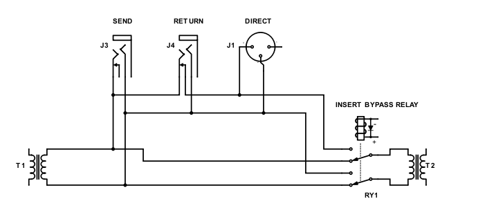
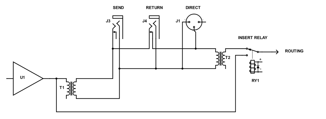
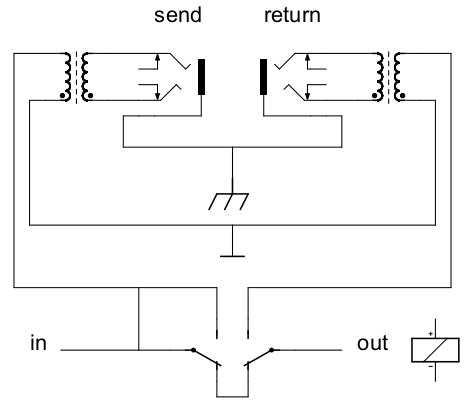
Suppose you have a mixer with a balanced insert, achieved by using transformers. So it goes unbalanced from the mixer via a transformer to the insert send then from the insert return via another transformer to the unbalanced mixer circuits.

If you want to switch this insert in or out, is it better/preferred to do it one the balanced side, keeping the transformers in circuit even when the insert is switched out, or on the unbalanced side thereby eliminating the path through the two transformers?

Cheers

Ian

Edit: Back in the day at Neve this was never and issue. Inserts were not switched so both transformers were always in circuit.
 
"keeping the transformers in circuit even when the insert is switched out"
Not sure if this helps at all, being quite ignorant of the usual methods, but I've made an assumption in my patch flow that all inserts assume balanced signal input and return from devices that have their own balanced tx out.  I am not tapping from any signal that is unbalanced in my input card so as to reduce the chance for noise (and because I don't know enough to go rocking the apple cart).

This of course limits where and how many inserts are available on my desk, but any unbalanced inserts I imagine needing I figure would want some decent preamp anyway, therefore they can go in early (100% source) or late (rerouted from direct out to another channel) in the chain if necessary, but I'll avoid the middle between my two amp stages around the fader.
If it's an fx loop chain of multiple mixed (balanced/unbalanced) devices, then signal will be split and sent from a bus group or aux where it's unbalanced anyway, before circling back to whichever aca is appropriate. If no blend is necessary, then I'll mute the source channel.
 
boji said:
Not sure if this helps at all, being quite ignorant of the usual methods, but I've made an assumption in my patch flow that all inserts assume balanced signal input and return from devices that have their own balanced tx out.  I am not tapping from any signal that is unbalanced in my input card so as to reduce the chance for noise (and because I don't know enough to go rocking the apple cart).
I think basically you are saying all inserts should be balanced and I agree with that. But do you include the ability to switch an insert in or out? A lot of people seem to think this is necessary these days so they can compare the original with the effected via insert sound. Like I mentioned, in the good old days this was never an issue because it was not an option.

Cheers

Ian
 
I agree that having switched inserts is a good thing.

I've always found transformers to change the sound, often in a pleasing way but not always. So it would in part depend on how everything sounds with the transformers always connected.  If it's a net positive or just neutral sounding then keep them in and switch after the transformers.

Switching before the transformers might give you more options though. It's a cleaner signal path and a little more versatile as you really end up with 3 different colors:
1) no transformers
2) just transformers, as you can run the outboard in bypass or just use a jumper cable
3) transformers and outboard

Not sure there is a clear winner between the two options.
 
But do you include the ability to switch an insert in or out?

Most definitely, but they are relay driven coming off of two 500 slots (I imagine not applicable in your case) as well as one on the first output stage of the input card, which is to say, they are not switching in/out transformers specifically in place just to handle inserts. 
However, I could see a need for these if the console is being sold to someone else and you need to compensate for user 'creativity'.
 
80hinhiding said:
I'm curious why it wasn't done with a switch?

Adam

Back in the 70s, most pro consoles came with a built in patch bay. All the pairs of contacts were half normaled. So if you wanted to hear the clean sound you simply pulled out the 'sniff' cable.

The other thing is I suspect the way of working in those days was rather different. There was not the huge range of insert FX that we have today.

Cheers

Ian
 
Rob Flinn said:
If you had the transformer insert half normalised on a patchbay & a pre transformer insert switch you would have both options available ...

I think perhaps I did not explain myself properly. I had assumed the insert would be half normaled - that's what a balanced insert means doesn't it? - or am I so out of date that people don't build inserts that way any more?

And given that. I am still not clear what two options would be available?

Cheers

Ian
 
I am still not clear what two options would be available?

I think my question was hidden in a word salad earlier:  Can you omit the extra transformers, utilizing ones that are part of the path of the main circuit? Because if your insert returns are balanced or not, they would be made unbalanced and return to the fader that wants unbalanced anyway.  If the insert is being sent off a tx that is driving the fader, then the send could be balanced or unbalanced depending on the jack what kind of cable goes into it.  I suppose this only relates to one of many insert points... In this section a choice might be to either half normal the jacks or use a relay/switch to keep the signals near the amps when no insert is needed, then you'd get your A/B comps too.

Edit: In retrospect I probably should have just kept my yap shut, since I have no knowledge of tube console topology. Since all I know is what I'm working on (and little at that) I'm assuming an API-type console signal flow.  /meep
 
How about putting the switch before the transformer but only on the return side.? Kind of like a half normal. That way you would have a dual use  port.  A balanced direct out and an insert send.

Edit: Scratch before the transformer. I think the functionality is right but the switch would have to be after the transformer.  That way you could have something plugged into the return and not hear it.
 
ruffrecords said:
I think perhaps I did not explain myself properly. I had assumed the insert would be half normaled - that's what a balanced insert means doesn't it? - or am I so out of date that people don't build inserts that way any more?

And given that. I am still not clear what two options would be available?

Cheers

Ian

Let me clarify. 

Scenario 1. You have the insert switch before the out transformer & after the in transformer.  When you switch the insert out with the switch the transformers are not part of the equation. 
Scenario 2.  The insert point is switched in with the switch, but because it is half normalled on the patchbay both in & out transformers are in line.  If you want to bypass the piece of gear that is inserted you just pull the return patch lead.

This way with out an effect inserted by the use of the switch you can eaither have the transformers in line or not.

Do you now see the 2 options ?
 
Rob Flinn said:
Let me clarify. 

Scenario 1. You have the insert switch before the out transformer & after the in transformer.  When you switch the insert out with the switch the transformers are not part of the equation. 
Scenario 2.  The insert point is switched in with the switch, but because it is half normalled on the patchbay both in & out transformers are in line.  If you want to bypass the piece of gear that is inserted you just pull the return patch lead.

This way with out an effect inserted by the use of the switch you can either have the transformers in line or not.

Do you now see the 2 options ?

I do see them!!  The key is, if there is nothing inserted in the patch bay you can switch between transformers and no transformers. Hmmm. Pretty neat. Thanks for that.

Cheers

Ian
 
porkyc said:
The insert TX is always live. The insert return is switched after the balanced RX circuit.

Got it. Pointless disconnecting the TX side because it can double up as a direct out. I knew there was an obvious answer. Thanks.

Cheers

Ian
 
porkyc said:
The insert TX is always live. The insert return is switched after the balanced RX circuit.
That's exactly what I did in my channel strips. The insert is bypassed completely, before the tx / rx circuits (THAT 1206 / THAT 1646 respectively), by a relay but there is a jumper that just makes the send always hot. This is very useful because you can effectively split a signal for parallel processing.

But then I also added another relay that swaps the insert send with the main output of the channel on the back. When activated, that gives me a nice stand-alone mic pre / line in that runs out the back and then the insert is IO for everything that comes after (compression / eq). Although this is probably more useful to me only because my channels have all different circuits so it enables me to mix and match different pres / compression / eq in whichever way.

But wait, there's more! I also have a group of relays that can swap the first and last two of three circuits. Meaning I can do:

insert -> compression -> eq
compression -> insert -> eq
insert -> eq -> compression

This can be done with only 3 relays. With 2 bypass relays, the 1 swap out relay I mentioned and 1 mute relay, the board has a total of 7 relays (and relay driver IC on the board handles 8 so I use the extra driver for another relay elsewhere). So there's quite a lot of functionality in one little board.
 
Thanks for the inputs everyone. Here is what I propose to do at present:

Channel-_Insert-_Switching.png


T1 is the output transformer of the channel. RY1 and T2 are in the routing module.

T1 output is fed to the half normal send and return jacks J3 and J4. J4 is also paralleled with the direct out XLR J1. With insert bypassed (as shown) T1 is connected directly to T2 so the insert is disconnected from the channel signal flow.  But the insert is still also connected to T2 output so the direct out still gets the channel out plus anything inserted.

When the relay is in the other position, T2 receives the output of the insert.

Cheers

Ian
 
squarewave said:
Why not put the bypass outside the transformers? Even if it's a tube circuit, it seems you could add a cap or two to isolate.

That is exactly the question I asked in the first post!! I was thinking of doing it this way:

Channel-_Insert-_Switching-unbalanced-1.png


I was thinking of having an insert PCB at the back of the mixer that would hold the relay,  output and input transformers and connectors. You could make various versions depending on which components you included

Cheers

Ian
 
For some reason when I try to load your schematic into my brain I get a bus error.

What is the normally contact of J4 doing? Could it be that you have the normalling contact and tip reversed? As it is the tips and rings of both jacks are connected regardless of switching / normalling. Why do you even want to use the normally contact at all? Do you really want it to still pass signal if the return is pulled out when you could just deactivate the insert relay?

Why not just do something like this:

Screenshot%2Bfrom%2B2018-06-27%2B13-05-17.png


Although the phase is wrong in my drawing. Fix accordingly.
 

Latest posts

Back
Top