Bandaid filters -vocal pop remover & hum injector

GroupDIY Audio Forum

Help Support GroupDIY Audio Forum:

This site may earn a commission from merchant affiliate links, including eBay, Amazon, and others.

Freq Band

Well-known member
GDIY Supporter
Joined
Jan 5, 2006
Messages
608
Location
Electra City
I came across these filters on the net, by Ethan Winer (1981):
FULL ARTICLE:
http://www.ethanwiner.com/filters.html
Vocal Pop Filter and Hum Injector/Remover

(is there a way to reduce the size of this image??)

I realize that in today's world, these problems are easily overcome on a computer, after the recording. And that the best way to remove hum, is at it's source, before recording. But I will be making these portable and battery operated (more about this further), for location recording. An adequate pop shield is preventetive, but not always practicle in the field..."on the fly" if you will. even in the studio, there will always be the time when the "performer' could "pop" directly into the mic (instead of the preferred "singing across the mic).
I'm not even sure if these are usefull enough, but I'm building them, and your comments here are welcome.

Some newbie Q's:
1) How to configure the filters to be used in a balanced setup ?
2) (from above) Will the Hum injector work from batteries?
3) Which opamps to be used in Hum filter ?
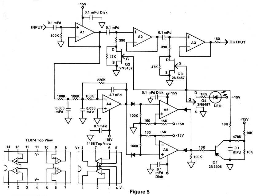
4) The unmarked pad at the bottom of A6 is to be -15v ? (pop schematic)
5) I have Jfet 2n3819's on hand...instead of the 2n5457 ??

Pop Filter:
filter-5.jpg


=FB=
 
Balanced input maybe?:
http://www.ethanwiner.com/meters-2.jpg

Never mind the rest of the circuit, look at the alternative input part of the diagram. Is this how?
What about output?

=FB=
 
Answers to your questions:

1. Use a differential amplifier such as the SSM2017 or INA217 at the front. See their data sheets for how to wire them up. Alternatively, you could make a lower-performance one from an opamp and four resistors as the link in the previous post illustrated.

2. Yes, but there's no point as you need the mains transformer to give you the reference frequency.

3. Almost any audio opamps will work here, so you could use TL074s as in the pop ducker.

4. Yes, that should be -15V and so should the rail marked as +15V at the top of the 10K divider if you stick with N-channel FETs.

5. The 2N3819 should work but you may have to change the 10K/10K divider to 12K/8.2K (12K to ground).
 
[quote author="Boswell"]Answers to your questions:

2. Yes, but there's no point as you need the mains transformer to give you the reference frequency.

4. Yes, that should be -15V and so should the rail marked as +15V at the top of the 10K divider if you stick with N-channel FETs.[/quote]

Thanks Boswell,

2) ...this was my concern.

4) ...top of the divider being (next to r 470k)?

p30a_f4.gif


or this......

p30a_f5.gif

(above images: credit to Rod Elliot, ESP)
or this...
http://www.dself.dsl.pipex.com/ampins/balanced/balfig9.gif
(credit: Doug Self)
 
The 470K is the middle of the divider. The original schematic you posted showed the upper 10K resistor connected to +15V when it should have been -15V.

On paper, your three difference circuits are all similar. Using an SSM2017/INA217 guarantees you a high common-mode rejection ratio (CMRR) because the bridge resistors are internal and trimmed to a high accuracy. Both your other circuits had discrete resistors for the critical bridge function (R6 - R9), and you would have a job to match those yourself to get the same amount of CMRR. The balfig9 link you gave is the same circuit as the first amplifier but without the differential gain stage in front. This stage not only gives differential gain to improve the CMRR but removes the effect of source impedance imbalance on CMRR. For interest, this 3-opamp circuit is called the "classic instrumentation amplifier".
 
Boswell, I really appreciate your help, thx again...
I am thinking of using this "Superbal" input, but am wondering if a dual 1458, or 5532 will work ?

http://www.dself.dsl.pipex.com/ampins/balanced/balfig12.gif
(link credit, Doug Self)

....as for the output, I have some op471 quads, with a circuit found on it's datasheet, (figure 15, page 11):

http://www.analog.com/UploadedFiles/Data_Sheets/151309759OP471_a.pdf
Am I headed onto pleasure, or frustration?

=FB=
 
The "superbal" circuit is used in instrumentation applications when it is necessary to have equal common-mode and differential input impedances at the inverting and non-inverting inputs. All the extra amplifier is doing is altering the impedance at the non-inverting input for differential signals by creating a second virtual earth, and it doesn't remove the obligation to have accurately matched bridge resistors. You may be able to guess that I don't think it's worthwhile using for this application, since if you want a precision input, you would use one of the first two input circuits (SSM2017 or 3-opamp configuration) anyway.

By all means use the electronic transformer configuration for the output. This is a good circuit for balanced line driving. It's available in integrated form in the AD SSM2142.
 
Back
Top