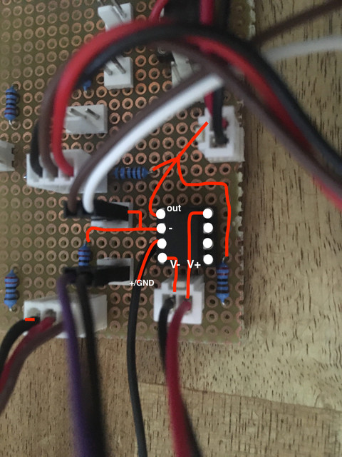
Baxandall Eq circuit, any comments?

GroupDIY Audio Forum

Help Support GroupDIY Audio Forum:

This site may earn a commission from merchant affiliate links, including eBay, Amazon, and others.
hazel said:
Did you try it first following schematic without variable caps?

yes and because that made no difference, i connected a switch with several values but neither does this
when i compare the bypassed signal with the circuit activated, i hear slightly elevated highs and lows but like i said, VR1/2 seem to have no influence..

i just replaced the potentiometers with higher values but no change...
 
.. and you connected to pins 1,2,3,4,8 or 4,5,6,7,8 of the dual opamp NE5532 (ignoring you might have left the unused opamp floating) ? Your pic seems to show a mixed up wiring of the opamp halfes ...
 
Harpo said:
.. and you connected to pins 1,2,3,4,8 or 4,5,6,7,8 of the dual opamp NE5532 (ignoring you might have left the unused opamp floating) ? Your pic seems to show a mixed up wiring of the opamp halfes ...

yes i connected 12348 and omitted 567. Is that a problem?

here is my wiring from top


whole board
 
weiss said:
thank you guys,

the pots are not making noise or anything. i bought them new, they should be fine.
i wired the 0v connection to pos. input of the opamp (pin 3) but nothing changed.
i replaced the NE5532 with a LM4562 but no change.

There is also no difference if i disconnect power ???
How have you connected the XLR's?
 
Matador said:
These math analysis are good for determining the behaviour at extreme settings; in-between, the various interactions make it difficult. In particular, evaluating the slope  and actual turnover frequency at moderate settings is quite tough. Simulation gives much more significant results; in particular, by stepping the position of the potentiometers, it clearly shows the difference in behaviour between the single and dual-cap implementations.
 
abbey road d enfer said:
How have you connected the XLR's?
wired it for unbalanced line

2 to the board (+)
1+3 connected (- and GND)

Matador said:

Thanks! I read the article from 1952, that's how i came across this circuit in the first place although i'm not really keen on working through the whole math behind it...  i'm happy when i get this thing to work
 
weiss said:
wired it for unbalanced line

2 to the board (+)
1+3 connected (- and GND)

Thanks! I read the article from 1952, that's how i came across this circuit in the first place although i'm not really keen on working through the whole math behind it...  i'm happy when i get this thing to work
From the last picture, it seems the opamp's output is not connected to R2 & 5.
 
abbey road d enfer said:
From the last picture, it seems the opamp's output is not connected to R2 & 5.

it is. 1 of the opamp meets with R2 and R5 and then goes to the output of the board.
 
abbey road d enfer said:
These math analysis are good for determining the behaviour at extreme settings; in-between, the various interactions make it difficult. In particular, evaluating the slope  and actual turnover frequency at moderate settings is quite tough. Simulation gives much more significant results; in particular, by stepping the position of the potentiometers, it clearly shows the difference in behaviour between the single and dual-cap implementations.
This is true, but one needs to start somewhere.  ;D

I've found that the math gives a good starting point, especially if you know the source impedances, and start at reasonable starting points for gain and centering the controls (like keeping the bass and treble control turn points at least one decade apart, etc).
 
abbey road d enfer said:
Well, I see you have only two wires coming from the PSU! You should have 3, one for positive voltage, one for negative and one for zero-volt ("ground")! That means the circuit is not powered correctly.

+1
 
weiss said:
it is. 1 of the opamp meets with R2 and R5 and then goes to the output of the board.
Then I'm out of suggestions. This is such a simple circuit it should work at the first time. I can only think of your actual hardware not being conform with your schematic. Check for crossed wires, misplaced connections, short or open circuits.
 
weiss said:
i wired the 0v connection to pos. input of the opamp (pin 3) but nothing changed.

That is audio ground, you need the differential on the supply.

weiss said:
There is also no difference if i disconnect power ???

Fairly certain this is just another symptom that your opamp is not powered.

Gustav
 
abbey road d enfer said:
Then I'm out of suggestions. This is such a simple circuit it should work at the first time. I can only think of your actual hardware not being conform with your schematic. Check for crossed wires, misplaced connections, short or open circuits.

Gustav said:
That is audio ground, you need the differential on the supply.

Fairly certain this is just another symptom that your opamp is not powered.

Gustav

thank you for your help again!
I think i am a bit closer.

When i disconnected the connection from psu middle connection to the op amp distortion appeared but i am able to change tone with the controls! When i connect it back i can't hear a difference with the tone controls and the distortion disappears. Also when i turn power off the tone control gets disengaged!

Where should the connection from the + pole of the opamp go? when i connect it to the xlr - i get even worse distortion...
It is only distorting low signals

boji said:
+1

Do you have access to a dual power supply?

https://www.youtube.com/watch?v=mJL11UF1arQ

nope, i only got the transformer and my psu
 
Gustav said:
That is audio ground, you need the differential on the supply.

Fairly certain this is just another symptom that your opamp is not powered.

Gustav

i always thought that audio ground and voltage ground use the same connection?
 
weiss said:
i always thought that audio ground and voltage ground use the same connection?
This is approximately true, but your issue is that you need a bipolar PSU, i.e. one that delivers both a negative and a positive voltage in reference to a common zero-volt reference. You would then connect the audio ground to the 0V reference point of the dual PSU.
 
abbey road d enfer said:
This is approximately true, but your issue is that you need a bipolar PSU, i.e. one that delivers both a negative and a positive voltage in reference to a common zero-volt reference. You would then connect the audio ground to the 0V reference point of the dual PSU.


but that is what i did? i have +15V 0V and -15V from the PSU (Volker's PosNeg PSU rev02) going to the opamp...
 
Pusch3l said:
Looking at your picture I can see the 0v isn't connected anywhere on your testboard.

It's there. Check reply #22. It is the black cable labeled with GND going to the bottom.
 

Latest posts

Back
Top