Bo Deadly
Well-known member
I found an old Rocktek Chorus pedal and decided to take a dive into it.
Apparently it's just a Boss CE-2 near as I can tell. Same chips, same LFO but with it's own virtual ground (I guess to isolate the trigger amp).
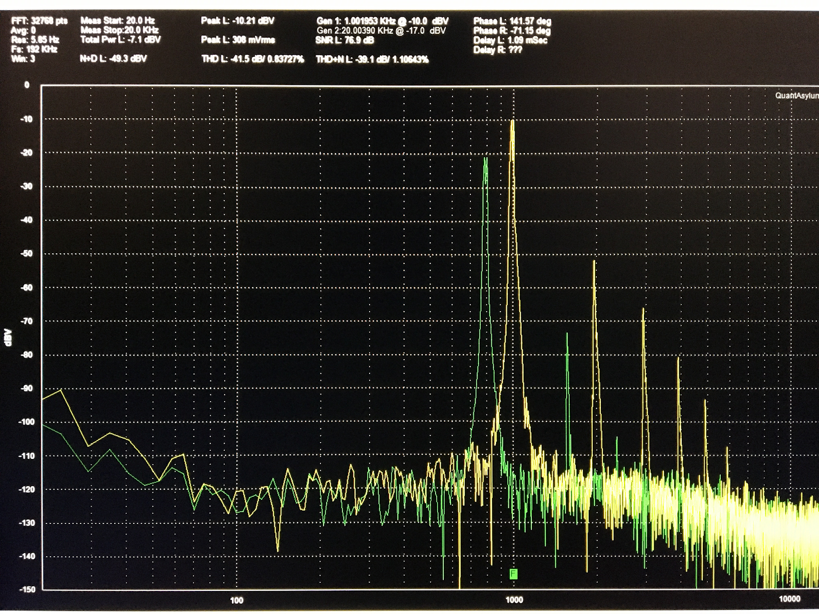
So I thought I would try to fix it up as best I can and play around with it. CE-2 sells for 100+ but this this is literally going for 20. Yeah, it might be a plastic box but it's basically the same circuit. It works fine. I hooked it up to the analyzer and noise performance is surprisingly good.
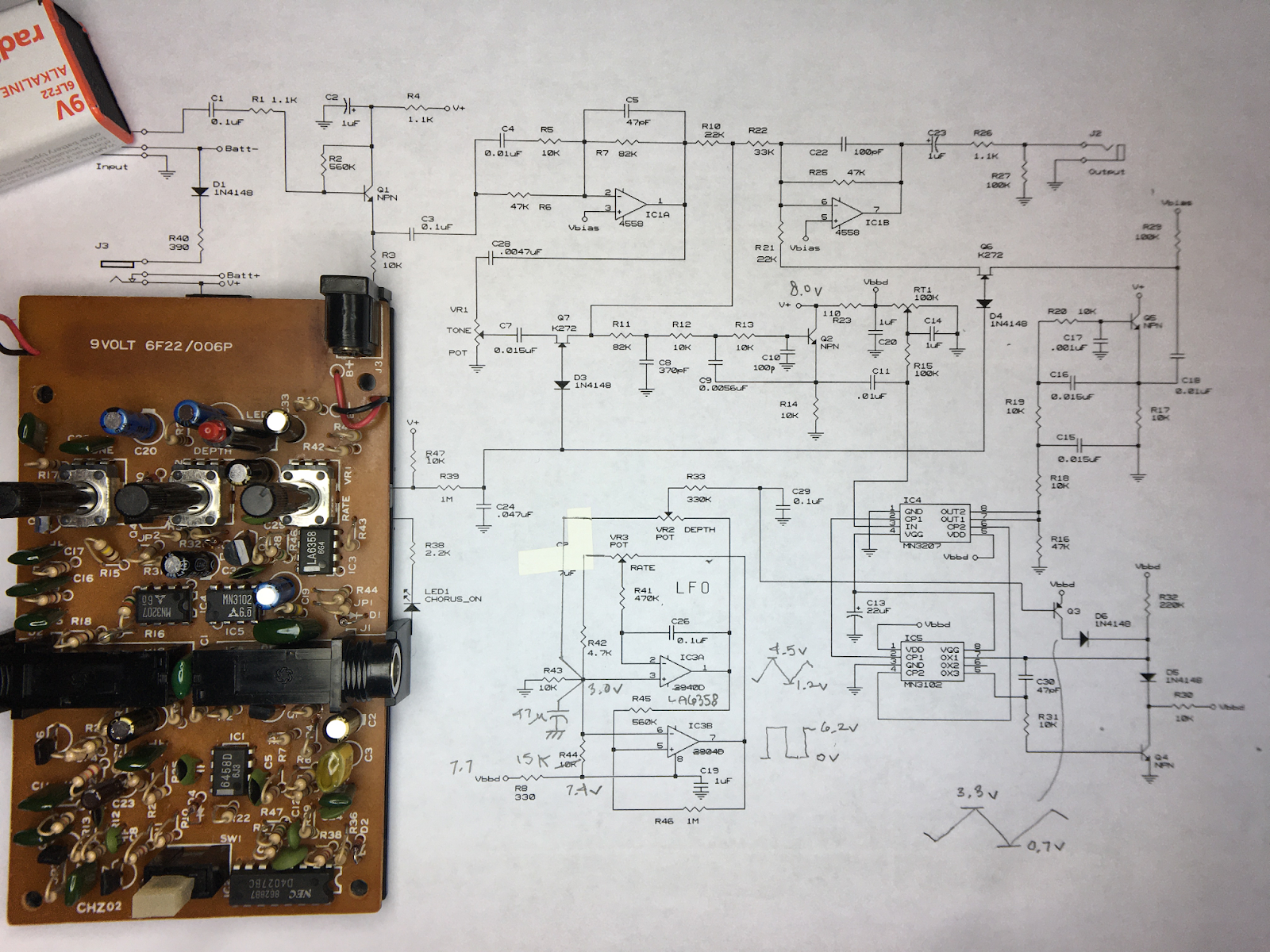
So I found a schematic (a little wrong / different - no BBD input bias trim - but a good start) and took some measurements:

As you can see, the battery is 8V, Vbbd is 7.4V and the LFO trigger amp out is a square from 0V to 6.2V which is about right for the LA6358. Then, the integrator is putting out a triangle from 1.2V - 4.5V and by the time it gets to the diode feeding OX1 of the BBD clock chip, it's a triangle from 0.7V to 3.3V.
Unfortunately I don't know anything about BBDs so I'm not sure if this is right. The CE-2 schematic claims the LFO virtual ground should be V+/2 but this is quite a bit lower at 3V which is only 40% Vbbd.
So my question is, is this working correctly and / or what can I do to improve things?
In particular, the LFO flops around a bit at the slowest speed (which isn't that slow - only around 1Hz). Is there a way to make this slower and smoother at slower speeds?
Apparently it's just a Boss CE-2 near as I can tell. Same chips, same LFO but with it's own virtual ground (I guess to isolate the trigger amp).
So I thought I would try to fix it up as best I can and play around with it. CE-2 sells for 100+ but this this is literally going for 20. Yeah, it might be a plastic box but it's basically the same circuit. It works fine. I hooked it up to the analyzer and noise performance is surprisingly good.
So I found a schematic (a little wrong / different - no BBD input bias trim - but a good start) and took some measurements:

As you can see, the battery is 8V, Vbbd is 7.4V and the LFO trigger amp out is a square from 0V to 6.2V which is about right for the LA6358. Then, the integrator is putting out a triangle from 1.2V - 4.5V and by the time it gets to the diode feeding OX1 of the BBD clock chip, it's a triangle from 0.7V to 3.3V.
Unfortunately I don't know anything about BBDs so I'm not sure if this is right. The CE-2 schematic claims the LFO virtual ground should be V+/2 but this is quite a bit lower at 3V which is only 40% Vbbd.
So my question is, is this working correctly and / or what can I do to improve things?
In particular, the LFO flops around a bit at the slowest speed (which isn't that slow - only around 1Hz). Is there a way to make this slower and smoother at slower speeds?


![Electronics Soldering Iron Kit, [Upgraded] Soldering Iron 110V 90W LCD Digital Portable Soldering Kit 180-480℃(356-896℉), Welding Tool with ON/OFF Switch, Auto-sleep, Thermostatic Design](https://m.media-amazon.com/images/I/41gRDnlyfJS._SL500_.jpg)


