Blowing 5534's....

GroupDIY Audio Forum

Help Support GroupDIY Audio Forum:

This site may earn a commission from merchant affiliate links, including eBay, Amazon, and others.

ramshackles

Well-known member
Joined
Dec 18, 2011
Messages
522
Location
Riorges, France
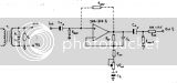
I've laid out a PCB which is essentially 4 seperate amplifiers and 2 transformers. Each 'block' is unconnected, following this schematic:
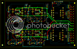


The PCB layout:


So, I've used the PCB to wire up a preamp according to the schematic attached (as a pdf). Im quite certain it is wired up correctly, although I neglected the decoupling capacitors on this first test. When I pass power through with no opamps in place, all the voltages look good and, yay, no smoke!
Then I popped in the 5534's and no! the second opamp starts smoking...

Any tips on how to troubleshoot? Im at a loss...


Attachments

  • buckbarrowpreamp.pdf
    28.9 KB
I once had a problem with the + and the - supply voltages not coming up at the same time.
Two anti-parallel diodes across the power supply lines cured the problem.
(Not sure if this is also your problem, but just for information...)
 
With no ICs installed, measure each pin to ensure +V appears **only** on pin 7, and -V appears **only** on pin 4.  Next, disconnect the PSU from the board and measure resistance from each pin to 0V/"ground".  The only path to 0V should be from pin 3 through whatever the "Rbias" value is, and you'll see the rail bypass caps charge as you probe the resistances from pins 4 and 7 to 0V/"ground".

I recall seeing 5534's scorch from an accidental short from pin 1 to 0V.

Bri
 
Brian Roth said:
With no ICs installed, measure each pin to ensure +V appears **only** on pin 7, and -V appears **only** on pin 4.  Next, disconnect the PSU from the board and measure resistance from each pin to 0V/"ground".  The only path to 0V should be from pin 3 through whatever the "Rbias" value is, and you'll see the rail bypass caps charge as you probe the resistances from pins 4 and 7 to 0V/"ground".

I recall seeing 5534's scorch from an accidental short from pin 1 to 0V.

Bri


Thanks, this all checks out. I did notice what could have been a cold solder (hard to tell), but it wasn't in a place that should make much difference. Anyway, I'll try and cover all the possible checks before popping another pair of 5534's back in...
 
JohnRoberts said:
positive feedback could make it oscillate but even that should not make it release smoke, unless also driving a low impedance load.

JR

RLaw is not fitted; there are quite q few components on the PCB/first schematic not fitted...the attached pdf shows how ive wired it up..
 
Yikes!!  That's why I had suggested you use a meter to verify that the PSU rails showed up ONLY on pins 4/7  AND that none of the other pins measured continuity to 0V!!

I now remember how I discovered that 5534 failure mode (pin 1 grounded).  MCI used Harris HA-911 (house marked as MCI 2001) opamps in their original 400 series desks.  Those round metal can opamps had pin 1 tied to the metal case, so MCI tied pin 1 to 0V on some (but not all) opamp sockets via PCB traces.

The HA-911 became obsolete decades ago, so people started retrofitting NE5534 opamps, which had essentially the same pinout.  That's when we discovered the "pin 1 scorch mode" for 5534's.  In the case of the MCI desks, that involved whacking the PCB foil loose from pin 1 of any opamp sockets which were tied to 0V.

Bri

 
This is the danger of the internet. I was wondering what to do with pin 1 as I wasnt going to do any offset/balance. A google came up with numerous answers saying 'ground all unused pins'...duh..

Of course, I should've just asked here :)

All right, I've disconnected pin 1 (bent the leg out of the way)...Ill turn it on after ive finished my breakfast :)
 
Thanks guys!!

Just turned it on and no smoke :). Nothing got hot after a few minutes, so success.

So now, the next problem:

I'm getting about -2.9 volts on the output of each amp (+/-15V supply)... hmm. So I checked the inputs. On the first stage, I get -0.8 at the positive input and -1.6 at the negative. At the second stage I get about -2.8V at each input. So I have DC sneaking in.

I uploaded a slightly better schematic of how I've wired up the pcb (the zobel network and decoupling capacitors are not yet fitted. There is 22pf between pins 5 and 8 of the 5534's which isnt shown, and of course, pin 1 is now floating):


I thought you were using 5534 opamps...that latest schemo shows something else per the pin numbers.

Direct coupling the first opamp into the second will magnify any DC offsets....

Bri

 
A good schematic (all parts values filled in, correct opamp pin numbers and in readable size) would make things much easier...

What surely won't work is the secondaries of the input transformer--you'll need to connect them together (pin 6 and 8, if I'm reading the small numbers correctly).

Brian Roth said:
Direct coupling the first opamp into the second will magnify any DC offsets...

If I'm reading the schematic correctly both stages have unity DC gain, so overall DC gain is unity--nothing should get amplified.

Samuel
 
Sorry, pretty poor schematic as I quickly knocked it together to show connections/what parts are populated and what is not. It is not a 'working' schematic and was not used to create the board.

I've corrected it to more accurately reflect what I've done...
pins 1,5,8 are not shown

 
Why are you cascading (with DC coupling) two gain stages in series???

Are you planning to record houseflies farting in flight with a ribbon mic located four miles away????

IE, 20000000000000000000000000000000000 dB gain from in to out...

???

Bri

 
I wondered if that would come up...
I've essentially being following a schematic by samuel groner (from the datasheet for the SGA-SOA-1 discrete opamp) which has them dc coupled. But if this is a problem here, wouldnt it be a problem on the original?

I have included the capacitor and resistor to ground on the PCB so putting them in wont be a probem. 10uF and 22K will keep the -3db point.
 
Brian Roth said:
Why are you cascading (with DC coupling) two gain stages in series???

Are you planning to record houseflies farting in flight with a ribbon mic located four miles away????

IE, 20000000000000000000000000000000000 dB gain from in to out...
6dB from 1:2 stepup transformer + 40.85dB max.from 1st.gain stage + 23.90dB max.from 2nd.gain stage = 70.77dB max.gain.
I don't see anything wrong with this. Maybe missing something.
 
The TI data sheet shows NPN input devices and  an input bias current of 500nA typical so Ohms law will advice toe what voltage should be present at + input. 500nA X 6.8k in parallel with transformer winding DCR, or a very small (negative) DC voltage.

Since the + and - input voltages will be slightly negative, the DC blocking cap should have the + toward ground, but this reverse voltage will again be very small.


The feedback values look low impedance for my taste but whatever...

JR
 
Harpo said:
Brian Roth said:
Why are you cascading (with DC coupling) two gain stages in series???

Are you planning to record houseflies farting in flight with a ribbon mic located four miles away????

IE, 20000000000000000000000000000000000 dB gain from in to out...
6dB from 1:2 stepup transformer + 40.85dB max.from 1st.gain stage + 23.90dB max.from 2nd.gain stage = 70.77dB max.gain.
I don't see anything wrong with this. Maybe missing something.

Good... I came out at 72dB with my rough calculations so it's good to see I haven't gone completely loony...
 
Back
Top