Blowing 5534's....

GroupDIY Audio Forum

Help Support GroupDIY Audio Forum:

This site may earn a commission from merchant affiliate links, including eBay, Amazon, and others.
JohnRoberts said:
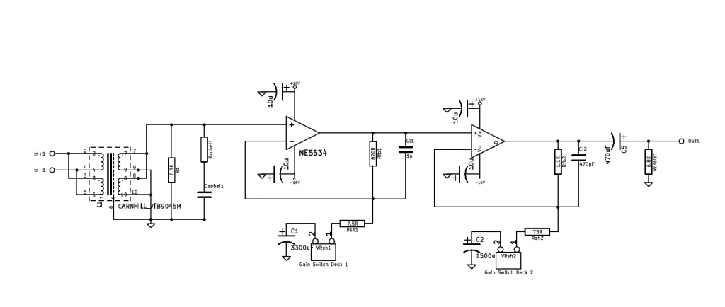
The TI data sheet shows NPN input devices and  an input bias current of 500nA typical so Ohms law will advice toe what voltage should be present at + input. 500nA X 6.8k in parallel with transformer winding DCR, or a very small (negative) DC voltage.

Since the + and - input voltages will be slightly negative, the DC blocking cap should have the + toward ground, but this reverse voltage will again be very small.


The feedback values look low impedance for my taste but whatever...

JR
Shouldn't be as high ~ -0.8V though should it?
 
So this works...sort of.
Two problems:

1. It only works if the solder lug(s) of the gain pot are connected to the chassis...otherwise it is just buzz. Grounding problem, but how to debug?
2. with the above 'fix' ...It seems to be either full gain or no gain - with the pot all the way up, I get nice, full gain. Anything else and nothing...I'm using a log pot where I should be using linear?
 
ramshackles said:
...It seems to be either full gain or no gain - with the pot all the way up, I get nice, full gain. Anything else and nothing...I'm using a log pot where I should be using linear?
The 'gain pot' is wired as a variable resistor/rheostat for each 'gain switch deck1' and 'gain switch deck2' from schematic.
Just run the numbers for some gain settings in order to see the rheostats value and taper needed at wanted rotation angle
for your (maybe stereo) pot with gain in dB=Log(1+Rfb/(Rsh+Rvar))*20.
Max.gain per stage is set with 0 ohm/shorted out gain switch/rheostat in series to Rsh.
For a more linear dB increase per pots rotation angle (pots come with high tolerances, taper might/will be far from perfect,...),
maybe use a max.rheostat value of Rfb-Rsh, giving a min.+6dB gain per gain stage.
I'd ignore the theoretical 0dB min.gain setting by infinite resistance/open connections at the gain switches,
so the (unity gain stable compensated) opamps would operate as unity gain followers instead, but YMMV.
 
Harpo said:
ramshackles said:
...It seems to be either full gain or no gain - with the pot all the way up, I get nice, full gain. Anything else and nothing...I'm using a log pot where I should be using linear?
The 'gain pot' is wired as a variable resistor/rheostat for each 'gain switch deck1' and 'gain switch deck2' from schematic.
Just run the numbers for some gain settings in order to see the rheostats value and taper needed at wanted rotation angle
for your (maybe stereo) pot with gain in dB=Log(1+Rfb/(Rsh+Rvar))*20.
Max.gain per stage is set with 0 ohm/shorted out gain switch/rheostat in series to Rsh.
For a more linear dB increase per pots rotation angle (pots come with high tolerances, taper might/will be far from perfect,...),
maybe use a max.rheostat value of Rfb-Rsh, giving a min.+6dB gain per gain stage.
I'd ignore the theoretical 0dB min.gain setting by infinite resistance/open connections at the gain switches,
so the (unity gain stable compensated) opamps would operate as unity gain followers instead, but YMMV.

Thats here: https://docs.google.com/spreadsheet/ccc?key=0AqLqEShkjOdRdDRMTnNVQVl5cTJQRWwtbmNQbGtEb1E&usp=sharing


The issue of buzz unless the pot is touching the chassis...I'm sure I've seen similar things on other threads, where the solution is always a simple/silly grounding issue... can't seem to find them now though..
 
ramshackles said:
Sorry, pretty poor schematic as I quickly knocked it together to show connections/what parts are populated and what is not. It is not a 'working' schematic and was not used to create the board.

I've corrected it to more accurately reflect what I've done...
pins 1,5,8 are not shown


My ancient eyeballs (and rickety/ancient laptop screen) can't discern the resistor values.  In any case, any DC offset from the output of the first opamp stage will be amplified by the gain of the second opamp stage, since they are DC coupled.

Bri

 
Ok...new developments. Good progress made, but why I'm not sure.

Both the problem of large DC voltages and buzzing unless the pot's solder lugs were against the chassis are gone. Here's what I have done:

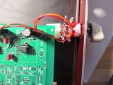
1. I suspected the power earth pin connection to the chassis to be loose...can't be sure if it was/wasn't making a connection (after the results I got I suspect it wasnt), but I replaced the wire and reconnected it using these:


(BTW, the name of those things escapes me, which is annoying as I need to buy more...)

2. I fitted a that1646 at the output to give a balanced output..

The buzz has gone away and the DC voltage at the inputs of each opamp is now <10mV and <20mV at the output of the second opamp...

a log pot is also clearly not the right way to go. The volume stays very quiet for most of the travel, before jumping up in the last 20 degrees or so.. (I wonder if I can strap a resistor across the lugs to modify the taper?)


Finally:
1. at max gain, there is still a low-level buzz as well as an odd squealing/pitch-shifting sound. The squealing gets louder/changes pitch if I touch the transformer casing...
2. There is a buzzing from the output when the power is off, which goes away when the power is on.....
 
ramshackles said:
a log pot is also clearly not the right way to go. The volume stays very quiet for most of the travel, before jumping up in the last 20 degrees or so.. (I wonder if I can strap a resistor across the lugs to modify the taper?)
As RuudNL already said and your spreadsheet shows, you want a rev.log. taper stereo pot. Unfortunately you can't mimic a rev.log taper by paralleling a slugging/law bending resistor when you want a clockwise decreasing resistive value. Using a two deck switch with stepped resistors for the wanted gain per step might be a lot easier than sourcing a maybe 1K stereo rev.log pot (maybe even with different values per pot deck to be a better match for your different 820R and 1K1 feedback resistors). A log taper pot/rheostat in series to a min.gain value setting feedback resistor would work, if you make sure the wiper never loses contact FI by a fixed resistor in parallel to the rheostat in order to prevent an open loop condition of a failing pot and the compensation cap in parallel to this feedback loop will need a 2nd.look.
 
You just reminded me that I had a switch already made up, doh! I'd wanted to test with pots for an easier-to-build/source and cheaper version. But as dual rev log pots are hard to find and pretty expensive anyway, not much point going down that road. And of course, it was designed for use with the switch, which has different values on each deck...so the pot was a silly idea really..

So I popped in the switch:


Works just fine, and funnily enough the squealy-sound at full gain has gone  :eek:. If I touch the input transformer it comes back, but is only audible really at full gain....

Perhaps now it is time to move on to doing some 'proper' testing and try and get some noise and distortion measurements...
 
The one on the right of the posted picture is often called a ring terminal:

https://www.google.com/#q=ring+terminal

A variant is often called a spade terminal:

http://www.allelectronics.com/make-a-store/category/196650/Crimp-Terminals/Spade-Terminals/1.html

Bri

 
ramshackles said:
Works just fine, and funnily enough the squealy-sound at full gain has gone  :eek:. If I touch the input transformer it comes back, but is only audible really at full gain....
Your device is still unstable.

One contributing factor is your earthing strategy (or lack of it).  You are using one earth for everything; dumping the noise on the power supply onto the earths used by your signal & feedback via the decoupling caps.

Another is almost certainly your layout.  There is a critical INPUT LOOP that should enclose the smallest possible area.  Its the path taken by your transformer connections to the +ve i/p of the 5534, the -ve i/p, Rsh1, VRsh1, C1 and back to the transformer connections.  R1 & your Zobel are also part of this loop.  Think of this like a Loop Aerial picking up crud.
___________

Lastly, you need a 100p NPO ceramic across R1 but this has to be AT the 5534.  You may need one for the 2nd 5534 too but that's complicated by it being fed directly from the 1st
 
ricardo said:
ramshackles said:
Works just fine, and funnily enough the squealy-sound at full gain has gone  :eek:. If I touch the input transformer it comes back, but is only audible really at full gain....
Your device is still unstable.

One contributing factor is your earthing strategy (or lack of it).  You are using one earth for everything; dumping the noise on the power supply onto the earths used by your signal & feedback via the decoupling caps.

Another is almost certainly your layout.  There is a critical INPUT LOOP that should enclose the smallest possible area.  Its the path taken by your transformer connections to the +ve i/p of the 5534, the -ve i/p, Rsh1, VRsh1, C1 and back to the transformer connections.  R1 & your Zobel are also part of this loop.  Think of this like a Loop Aerial picking up crud.
___________

Lastly, you need a 100p NPO ceramic across R1 but this has to be AT the 5534.  You may need one for the 2nd 5534 too but that's complicated by it being fed directly from the 1st

I don't exactly follow what you mean by 'earth'? To me that is the earth connection at the mains inlet...
There are 3 grounds in the system as I see it:
1. Safety earth
2. Chassis
3. Audio ground

They are all connected at 1 point which is via a bolt next to the earth connection of the main IEC connector.
You are saying that the power supply decoupling caps should not go to audio ground? Where to?

Not heard of an input loop before? It sounds like you are saying that the audio path goes back to the same transformer? I don't know if you are saying it should, or it does and it shouldn't. It definitley does not...
 
ramshackles said:
ricardo said:
One contributing factor is your earthing strategy (or lack of it).  You are using one earth for everything; dumping the noise on the power supply onto the earths used by your signal & feedback via the decoupling caps.

Another is almost certainly your layout.  There is a critical INPUT LOOP that should enclose the smallest possible area.  Its the path taken by your transformer connections to the +ve i/p of the 5534, the -ve i/p, Rsh1, VRsh1, C1 and back to the transformer connections.  R1 & your Zobel are also part of this loop.  Think of this like a Loop Aerial picking up crud.
___________

Lastly, you need a 100p NPO ceramic across R1 but this has to be AT the 5534.  You may need one for the 2nd 5534 too but that's complicated by it being fed directly from the 1st
I don't exactly follow what you mean by 'earth'? To me that is the earth connection at the mains inlet...
There are 3 grounds in the system as I see it:
1. Safety earth
2. Chassis
3. Audio ground

They are all connected at 1 point which is via a bolt next to the earth connection of the main IEC connector.
You are saying that the power supply decoupling caps should not go to audio ground? Where to?

Not heard of an input loop before? It sounds like you are saying that the audio path goes back to the same transformer? I don't know if you are saying it should, or it does and it shouldn't. It definitley does not...
There should be at least one other ground which is for your decoupling caps and other cr*p.  I pontificate on this and the Input Loop in a MicBuilders document, LNPrimer https://groups.yahoo.com/neo/groups/micbuilders/files/Ricardo/.  You have to join.

The Input Loop is the path the signal current must take.
_____________________

Try the 100p on the input of the 1st 5534 while you sort out the rest of it.
 
You group above is not open to anyone without a yahoo account and I'm not really inclined to set one up...

I've been reading about grounding all over this forum and especially thanks to ian's (ruffrecords) great document.

But there are a few things I see not done consistently which is maybe odd as there is surely one 'best' solution?

Take the common example of a single chassis with a power supply PCB and some kind analogue widget PCB. Just like I have. The way I see it there are 4 'grounds' to consider:

- Safety Earth
- Chassis
- Power common
- Signal reference.

There are couple of things which are largely agreed upon:
- Pin 1 of mic XLR's goes to the chassis and no where else (this is only violated for phantom power)
- Safety earth is connected to the chassis via a nice bolt close to the mains IEC connector.

What I often hear quoted is that other grounds should also meet up with the safety earth & chassis at the same point (the star point) and only at that point...

But what often seems to happen is that the power common is passed on to the audio widget PCB and connected to it's signal reference?

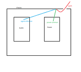
Is it better to keep power common separate and have it and the signal reference meet up at the star point, like so?:


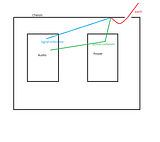
But the power common would still need to be passed on to the audio PCB (which I think is what ricardo is getting at) so power related components on the audio PCB can be grounded to the power common, not the signal reference? So the power common would be passed on to the audio PCB for this purpose, like so:

 
ramshackles said:
You group above is not open to anyone without a yahoo account and I'm not really inclined to set one up...
Suit yourself.
Is it better to keep power common separate and have it and the signal reference meet up at the star point, like so?:
Yes.  But it's not the whole picture.  Also read anything by John Roberts on the subject and spend some time trying to understand him.
___________________

On the separate but related subject of stability ...

Did you try 100p across R1 AT the 1st 5534?  Does it stop the squealing?
 
Back
Top