


blackartmixing
Active member
- Joined
- Dec 18, 2013
- Messages
- 34
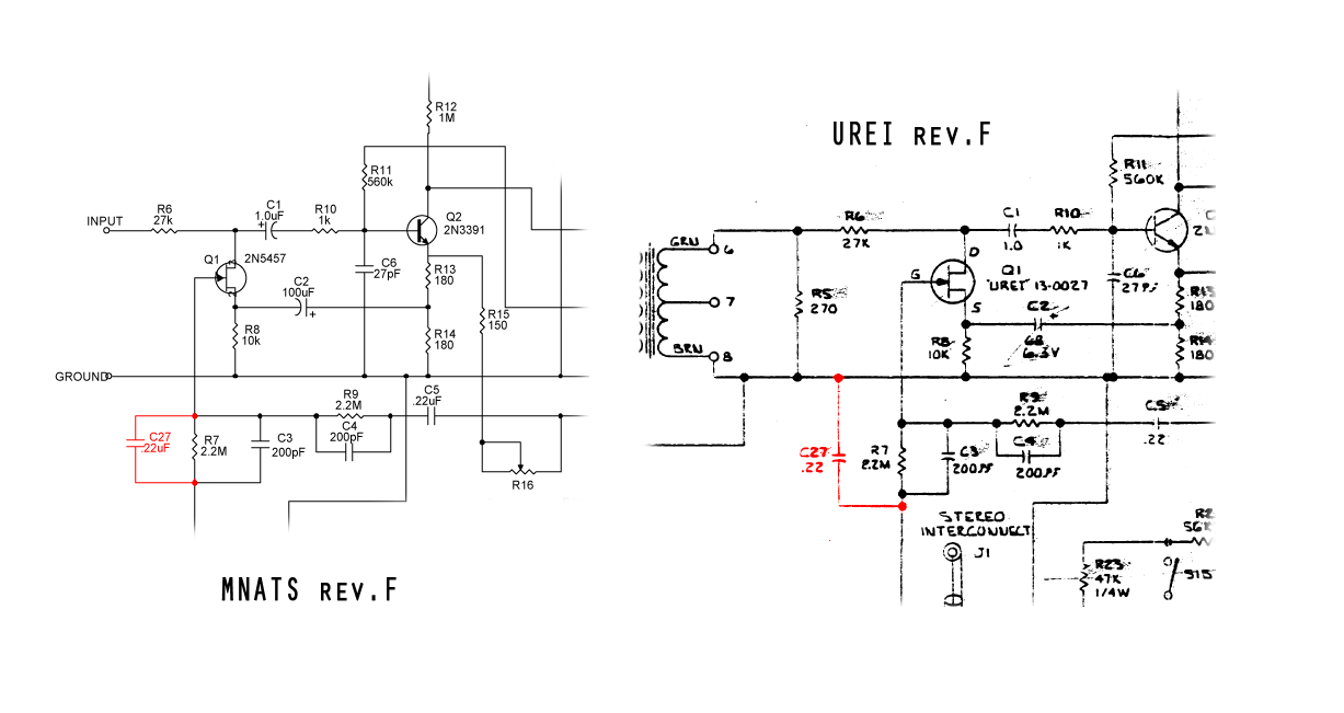
ok well i am still absolutely no closer to fixing my build. i have checked the wiring so many times now and cannot find anything wrong. just to re-cap, i checked all the voltages and all seems ok except maybe Q4
"the only place where is seems to be a bit suspect is Q4. i get 1.76 on the pin nearest the front panel, 4.18 on the middle and 12.73 on the far pin. according to the schematic it should be 6.6V and 13.72V so my values seems pretty low"
when i put a signal through the compressor is comes out clean with no distortion.
release and output knobs don't seem to be working as expected
i would like to avoid sending the whole thing back to the USA if possible but i'm running out of options. is ANYONE able to give me some support here? i'm desperate! this forum is really not very efficient although i do appreciate the help so far. if its not totally clear already i'm a complete noob with this stuff. thanks


![Soldering Iron Kit, 120W LED Digital Advanced Solder Iron Soldering Gun kit, 110V Welding Tools, Smart Temperature Control [356℉-932℉], Extra 5pcs Tips, Auto Sleep, Temp Calibration, Orange](https://m.media-amazon.com/images/I/51sFKu9SdeL._SL500_.jpg)


") so any further ideas to help me troubleshoot this?
so any further ideas to help me troubleshoot this?