Spencerleehorton
Well-known member
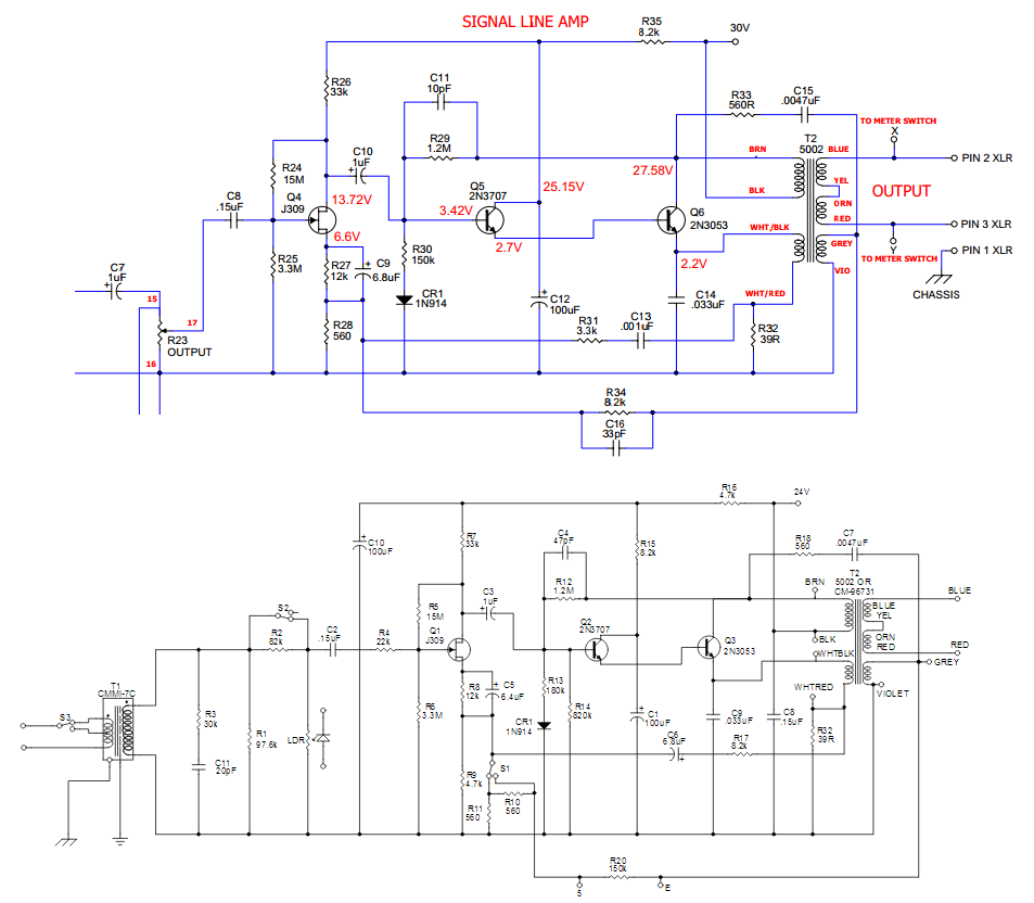
The problems im having are all due to not correct Q6 bias, also need to test psu for any ripple.
Spence.
Spence.


Spencerleehorton said:My other findings led me to change R32 to 280 ohm as my DCR of the Pri B winding was 20 ohms giving me a total of 300 ohms which is same as when using other transformer.
Then twiddle R29 to bias Q6 and take away distortion.
Heat wise on Q6 this is much better than before.
kessconn1 said:Hello all!
This is actually my first post to groupdiy so please pardon any forum etiquette mistakes. Anybody who has ever done the hairball blue stripe build I am in dire need of some assistance. A friend of mine purchased the kit and attempted it about a year ago, he eventually gave up and the non functioning unit was given to me. I know my way around a soldering iron and multi meter so figured I could get it working. So first off he made some pretty bad mistakes (ie backwards transistors incorrect resistor values) the fuse was blown. with replacement fuse power would not move past power transformer.
Soo, I decided to do a complete tear down, test and reassembly I opted to get a new pcb as well. Did not want to mess with his somewhat burnt original board. everything tested pretty well within tolerance except a few transistors, and maybe 1 cap... the only thing I was not able to properly verify were the two matched transistors on meter driver, and signal line amp. they passed voltage but i dont have a meter that will read transistors properly. all other transistors were replaced.
After my assembly was completed turned it on to verify signal and calibrate. All I got was hiss at around 10k . after some fooling i figured out that if i press all ratio buttons the unit passes signal. albeit very badly with hiss still there. The input pot did not seem to change the volume of this hiss, but output pot and meter seemed to be doing their job. attack and release knobs did nothing. I also noticed that if i put my hand over signal preamp the hiss geot much louder like there is a grounding issue.
I know this is a lot to throw at you guys but I would really like to get this running, and after tearing down and verifying every part I am a little lost. do not think I made any mistakes, have went back and triple checked wiring.... any way If anybody wants to aid a novice in need I would greatly appreciate it!
tata said:can anybody please help me whats the best way to get less amplification at the last stage?
i would like to use the Output pot (almost) fully, but in practice i only use the first half of it.
(Output is A250k potentiometer)
is 1/2W a must for the Output pot?
thanks
Hairball Audio said:Possibly a damaged a transistor.
What do your voltages look like?
http://mnats.net/files/1176REVA_125_VOLTAGES.pdf
Mike
Hairball Audio said:Possibly a damaged a transistor.
What do your voltages look like?
http://mnats.net/files/1176REVA_125_VOLTAGES.pdf
Mike
Potato Cakes said:It seems the less invasive permanent option to start with would be to wire the output transformer secondaries in parallel.
....
Again, I'm not exactly clear for what you're after, but I am curious if you do discover an audible difference between the output wide open and halfway. I think it would be good information to share with everyone here.
Thanks!
Paul
kessconn1 said:Hello Again, was able to sit down and read all voltages on transistors, here are all voltages listed, the readings are in this order
1st reading is transistor lead closest to front panel, second is center lead, third is lead closest to rear, hopefully this is ample for providing info needed, if you need me to label voltages by ECB let me know. here are readings:
q1: (-.32) (no rd)(no rd)
q2: (1.50) (4.34) (6.91)
q3: (6.41) (13.0) (6.4)
q4: (0.81) (4.60) (12.9)
q5: (2.72) (23.8) (2.9)
q6: (2.11) (2.6) (26.7)
q7: (4.40) (16.5) (4.4)
q8: (16.1) (29.2) (16.5)
q9: (2.9) (29.2) (16.5)
q10: (13.6) (13.9) (3.5)
q11: (-.12) (-.28) (3.17)
q12: (-1.2) (2.56) (-.66)
q13: (-1.2) (2.05) (-.67)
before you even respond i can see that some of the readings are a little off (q11-q13), but is till lack the know how to say what is causing this whether it is a bad transistor or something else in the circuit. any input would be greatly appreciated,
thanks!
Conner
Hairball Audio said:I mean I'm not going to go through and compare all of these to the schematic, but if you say only Q11-Q13 is off you're probably OK.
Did you re-use the Q6 from the previous build?
Mike


![Soldering Iron Kit, 120W LED Digital Advanced Solder Iron Soldering Gun kit, 110V Welding Tools, Smart Temperature Control [356℉-932℉], Extra 5pcs Tips, Auto Sleep, Temp Calibration, Orange](https://m.media-amazon.com/images/I/51sFKu9SdeL._SL500_.jpg)


