rhythminmind
Well-known member
- Joined
- Oct 20, 2009
- Messages
- 65
Finished up my 1st 1176, All Cal'd up & sounds/functions great.
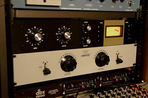
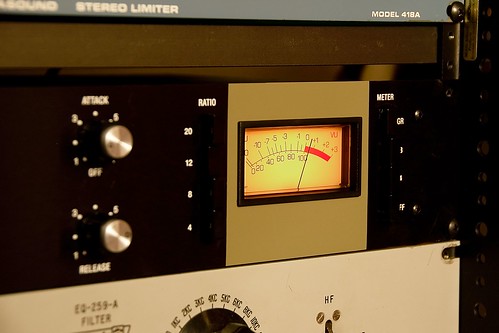


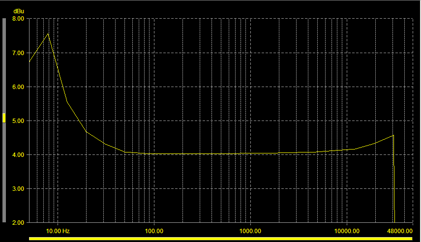

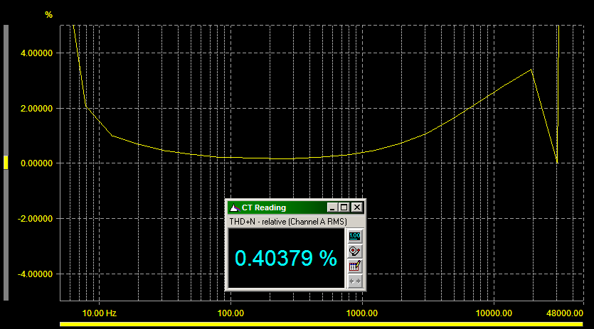

Frequency response +4 dbu (sharp cut off @ around 30khz was surprising)
Echo North said:For R10 you need a "link". You basically need to install a resistor leg or wire.
???Biasrocks said:Nothing like that here, clean output right to the top on my REV A.
I have mine terminated by a 620R resistor, try that.
Mark
Andy Meyer said:Hi guys,
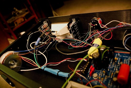
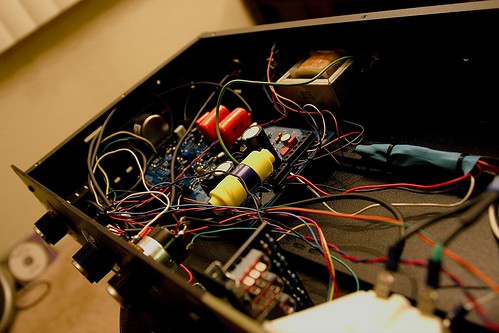
I have just assembled my Hairball + Mnats Rev A and have an issue. I don't get anything. I have checked the voltages at the 30v and -10v spots and both are showing 0v. I also checked voltages at the two AC and CT points on the PCB both showing 0v. I am getting 120v from the IEC power connector to the "Off" button on the meter board.
It seems like this leaves the transformer right? I am a newbie and could use some help.
Thanks in advance.
Andy


